Sensors
In Mitsuba 3, sensors, along with a film, are responsible for recording radiance measurements in some usable format.
In the XML scene description language, a sensor declaration looks as follows:
<scene version=3.0.0>
    <!-- .. scene contents .. -->

    <sensor type=".. sensor type ..">
        <!-- .. sensor parameters .. -->

        <sampler type=".. sampler type ..">
            <!-- .. sampler parameters .. -->
        </samplers>

        <film type=".. film type ..">
            <!-- .. film parameters .. -->
        </film>
    </sensor>
</scene>
'type': 'scene',

# .. scene contents ..

'sensor_id': {
    'type': '<sensor_type>',

    'film_id': {
        'type': '<film_type>',
        # ...
    },
    'sampler_id': {
        'type': '<sampler_type>',
        # ...
    }
}
In other words, the sensor declaration is a child element of the <scene>
(the particular position in the scene file does not play a role). Nested within
the sensor declaration is a sampler instance (see Samplers)
and a film instance (see Films).
Sensors in Mitsuba 3 are right-handed. Any number of rotations and translations
can be applied to them without changing this property. By default, they are located
at the origin and oriented in such a way that in the rendered image, \(+X\)
points left, \(+Y\) points upwards, and \(+Z\) points along the viewing
direction.
Left-handed sensors are also supported. To switch the handedness, flip any one
of the axes, e.g. by passing a scale transform like <scale x="-1"/> to the
sensor’s to_world parameter.
Spectral sensitivity. Furthermore, sensors can define a custom sensor
response function (SRF) defined as a spectral response function
<spectrum name="srf" filename="..."/> (it is possible to load a spectrum from a
file, see the Spectrum definition section). In other words,
it can be used to focus computation into several wavelengths. Note that this
parameter only works for spectral variants.
When no spectral sensitivity is set, it falls back to the rgb sensitivity curves.
On the other hand, it modifies the sampling of wavelengths to one according to the
new spectral sensitivity multiplied by the rgb sensitivity curves. Notice that
while using the High dynamic range film, the output will
be a rgb image containing only information of the visible range of the spectrum.
Another option is to use Spectral Film. By using it, it is
possible to define an arbitrary number of sensor sensitivities (SRF)
which do not need to be constrained to the visible range of the spectrum
(rgb sensitivity curves are not taken into account).
Orthographic camera (orthographic)
Parameter |
Type |
Description |
Flags |
|---|---|---|---|
to_world |
transform |
Specifies an optional camera-to-world transformation. (Default: none (i.e. camera space = world space)) |
P |
near_clip, far_clip |
float |
Distance to the near/far clip planes. (Default: near_clip=1e-2 (i.e. 0.01) and far_clip=1e4 (i.e. 10000)) |
P |
srf |
spectrum |
Sensor Response Function that defines the spectral sensitivity of the sensor (Default: none) |
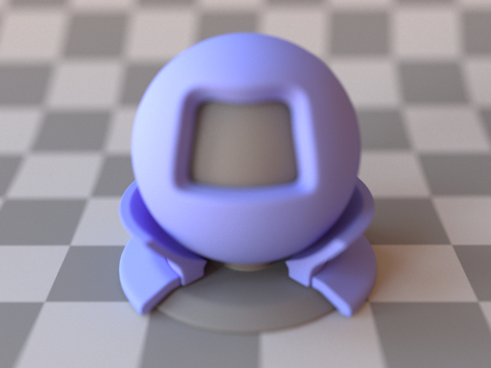
The material test ball viewed through an orthographic camera. Note the complete lack of perspective.)
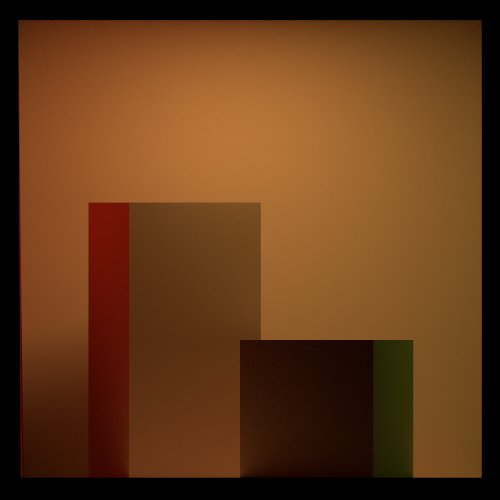
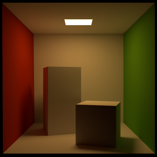
A rendering of the Cornell box
This plugin implements a simple orthographic camera, i.e. a sensor based on an orthographic projection without any form of perspective. It can be thought of as a planar sensor that measures the radiance along its normal direction. By default, this is the region $[-1, 1]^2$ inside the XY-plane facing along the positive Z direction. Transformed versions can be instantiated e.g. as follows:
The exact camera position and orientation is most easily expressed using the lookat tag, i.e.:
<sensor type="orthographic">
    <transform name="to_world">
        <!-- Resize the sensor plane to 20x20 world space units -->
        <scale x="10" y="10"/>

        <!-- Move and rotate the camera so that looks from (1, 1, 1) to (1, 2, 1)
            and the direction (0, 0, 1) points "up" in the output image -->
        <lookat origin="1, 1, 1" target="1, 2, 1" up="0, 0, 1"/>
    </transform>
</sensor>
'type': 'orthographic',
'to_world': mi.ScalarAffineTransform4f().look_at(
    origin=[1, 1, 1],
    target=[1, 2, 1],
    up=[0, 0, 1]
) @ mi.ScalarAffineTransform4f().scale([10, 10, 1])
Perspective pinhole camera (perspective)
Parameter |
Type |
Description |
Flags |
|---|---|---|---|
to_world |
transform |
Specifies an optional camera-to-world transformation. (Default: none (i.e. camera space = world space)) |
P, ∂, D |
fov |
float |
Denotes the camera’s field of view in degrees—must be between 0 and 180, excluding the extremes. Alternatively, it is also possible to specify a field of view using the focal_length parameter. |
|
focal_length |
string |
Denotes the camera’s focal length specified using 35mm film equivalent units. Alternatively, it is also possible to specify a field of view using the fov parameter. See the main description for further details. (Default: 50mm) |
|
fov_axis |
string |
When the parameter fov is given (and only then), this parameter further specifies the image axis, to which it applies.
The default is x. |
|
near_clip, far_clip |
float |
Distance to the near/far clip planes. (Default: near_clip=1e-2 (i.e. 0.01) and far_clip=1e4 (i.e. 10000)) |
P |
principal_point_offset_x, principal_point_offset_y |
float |
Specifies the position of the camera’s principal point relative to the center of the film. |
P, ∂, D |
srf |
spectrum |
Sensor Response Function that defines the spectral sensitivity of the sensor (Default: none) |
|
State parameters |
|||
x_fov |
float |
Denotes the camera’s field of view in degrees along the horizontal axis. |
P, ∂, D |
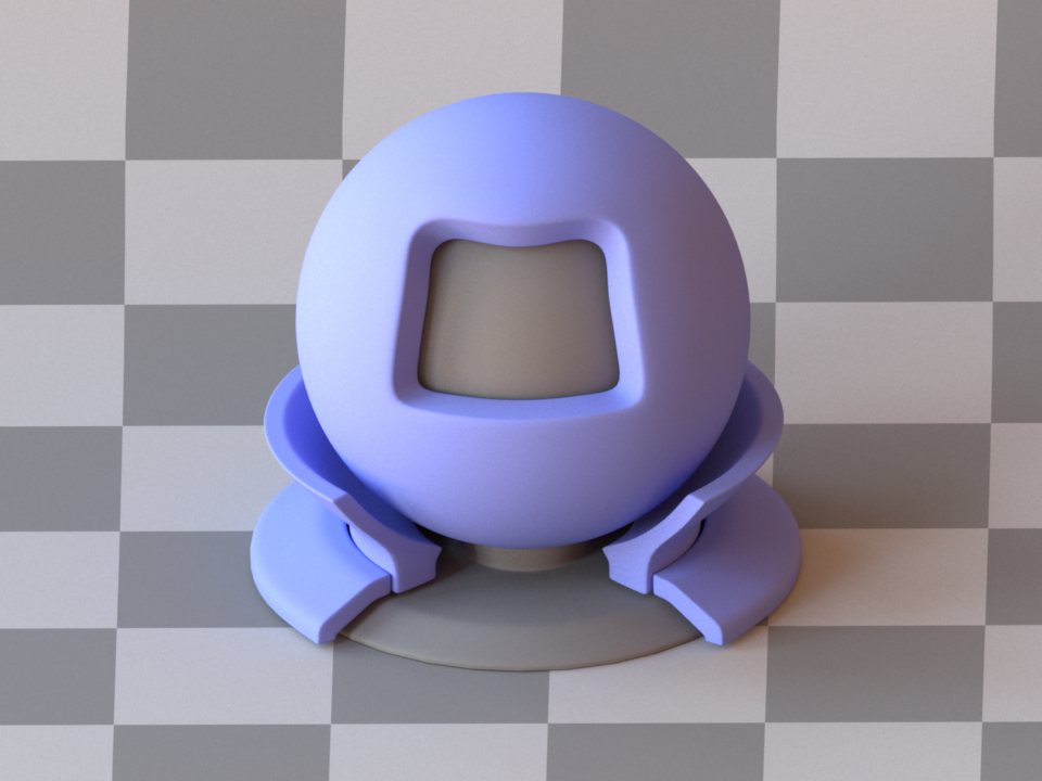
The material test ball viewed through a perspective pinhole camera. (fov=28)

The material test ball viewed through a perspective pinhole camera. (fov=40)
This plugin implements a simple idealized perspective camera model, which has an infinitely small aperture. This creates an infinite depth of field, i.e. no optical blurring occurs.
By default, the camera’s field of view is specified using a 35mm film equivalent focal length, which is first converted into a diagonal field of view and subsequently applied to the camera. This assumes that the film’s aspect ratio matches that of 35mm film (1.5:1), though the parameter still behaves intuitively when this is not the case. Alternatively, it is also possible to specify a field of view in degrees along a given axis (see the fov and fov_axis parameters).
The exact camera position and orientation is most easily expressed using the lookat tag, i.e.:
<sensor type="perspective">
    <float name="fov" value="45"/>
    <transform name="to_world">
        <!-- Move and rotate the camera so that looks from (1, 1, 1) to (1, 2, 1)
            and the direction (0, 0, 1) points "up" in the output image -->
        <lookat origin="1, 1, 1" target="1, 2, 1" up="0, 0, 1"/>
    </transform>
    <!-- film -->
    <!-- sampler -->
</sensor>
'type': 'perspective',
'fov': 45,
'to_world': mi.ScalarAffineTransform4f().look_at(
    origin=[1, 1, 1],
    target=[1, 2, 1],
    up=[0, 0, 1]
),
'film_id': {
    'type': '<film_type>',
    # ...
},
'sampler_id': {
    'type': '<sampler_type>',
    # ...
}
Perspective camera with a thin lens (thinlens)
Parameter |
Type |
Description |
Flags |
|---|---|---|---|
to_world |
transform |
Specifies an optional camera-to-world transformation. (Default: none (i.e. camera space = world space)) |
P |
aperture_radius |
float |
Denotes the radius of the camera’s aperture in scene units. |
P |
focus_distance |
float |
Denotes the world-space distance from the camera’s aperture to the focal plane. (Default: 0) |
P |
focal_length |
string |
Denotes the camera’s focal length specified using 35mm film equivalent units. See the main description for further details. (Default: 50mm) |
|
fov |
float |
An alternative to focal_length: denotes the camera’s field of view in degrees—must be between 0 and 180, excluding the extremes. |
|
fov_axis |
string |
When the parameter fov is given (and only then), this parameter further specifies the image axis, to which it applies.
The default is x. |
|
near_clip, far_clip |
float |
Distance to the near/far clip planes. (Default: near_clip=1e-2 (i.e. 0.01) and far_clip=1e4 (i.e. 10000)) |
P |
srf |
spectrum |
Sensor Response Function that defines the spectral sensitivity of the sensor (Default: none) |
|
State parameters |
|||
x_fov |
float |
Denotes the camera’s field of view in degrees along the horizontal axis. |
P |
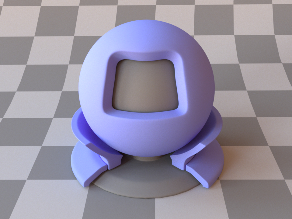
The material test ball viewed through a perspective thin lens camera. (aperture_radius=0.1)
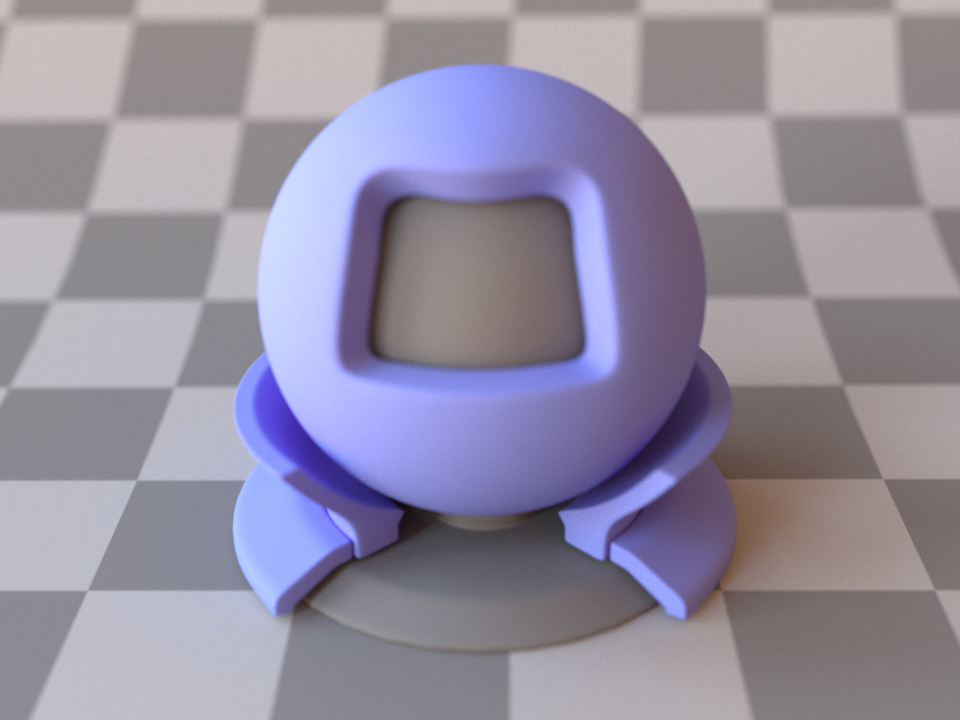
The material test ball viewed through a perspective thin lens camera. (aperture_radius=0.2)
This plugin implements a simple perspective camera model with a thin lens at its circular aperture. It is very similar to the perspective plugin except that the extra lens element permits rendering with a specifiable (i.e. non-infinite) depth of field. To configure this, it has two extra parameters named aperture_radius and focus_distance.
By default, the camera’s field of view is specified using a 35mm film equivalent focal length, which is first converted into a diagonal field of view and subsequently applied to the camera. This assumes that the film’s aspect ratio matches that of 35mm film (1.5:1), though the parameter still behaves intuitively when this is not the case. Alternatively, it is also possible to specify a field of view in degrees along a given axis (see the fov and fov_axis parameters).
The exact camera position and orientation is most easily expressed using the lookat tag, i.e.:
<sensor type="thinlens">
    <float name="fov" value="45"/>
    <transform name="to_world">
        <!-- Move and rotate the camera so that looks from (1, 1, 1) to (1, 2, 1)
            and the direction (0, 0, 1) points "up" in the output image -->
        <lookat origin="1, 1, 1" target="1, 2, 1" up="0, 0, 1"/>
    </transform>

    <!-- Focus on the target -->
    <float name="focus_distance" value="1"/>
    <float name="aperture_radius" value="0.1"/>

    <!-- film -->
    <!-- sampler -->
</sensor>
'type': 'thinlens',
'fov': 45,
'to_world': mi.ScalarAffineTransform4f().look_at(
    origin=[1, 1, 1],
    target=[1, 2, 1],
    up=[0, 0, 1]
),
'focus_distance': 1.0,
'aperture_radius': 0.1,
'film_id': {
    'type': '<film_type>',
    # ...
},
'sampler_id': {
    'type': '<sampler_type>',
    # ...
}
Irradiance meter (irradiancemeter)
Parameter |
Type |
Description |
Flags |
|---|---|---|---|
srf |
spectrum |
Sensor Response Function that defines the spectral sensitivity of the sensor (Default: none) |
This sensor plugin implements an irradiance meter, which measures the incident power per unit area over a shape which it is attached to. This sensor is used with films of 1 by 1 pixels.
If the irradiance meter is attached to a mesh-type shape, it will measure the irradiance over all triangles in the mesh.
This sensor is not instantiated on its own but must be defined as a child object to a shape in a scene. To create an irradiance meter, simply instantiate the desired sensor shape and specify an irradiancemeter instance as its child:
<shape type="sphere">
    <sensor type="irradiancemeter">
        <!-- film -->
    </sensor>
</shape>
'type': 'sphere',
'sensor': {
    'type': 'irradiancemeter'
    'film': {
        # ...
    }
}
Distant radiancemeter sensor (distant)
Parameter |
Type |
Description |
Flags |
|---|---|---|---|
to_world |
transform |
Sensor-to-world transformation matrix. |
|
direction |
vector |
Alternative (and exclusive) to |
|
target |
point or nested shape plugin |
Optional. Define the ray target sampling strategy. If this parameter is unset, ray target points are sampled uniformly on the cross section of the scene’s bounding sphere. If a point is passed, rays will target it. If a shape plugin is passed, ray target points will be sampled from its surface. |
|
srf |
spectrum |
Sensor Response Function that defines the spectral sensitivity of the sensor (Default: none) |
This sensor plugin implements a distant directional sensor which records
radiation leaving the scene in a given direction. It records the spectral
radiance leaving the scene in the specified direction. It is the adjoint to the
directional emitter.
By default, ray target points are sampled from the cross section of the scene’s
bounding sphere. The target parameter can be set to restrict ray target
sampling to a specific subregion of the scene. The recorded radiance is averaged
over the targeted geometry.
Ray origins are positioned outside of the scene’s geometry.
Warning
If this sensor is used with a targeting strategy leading to rays not hitting the scene’s geometry (e.g. default targeting strategy), it will pick up ambient emitter radiance samples (or zero values if no ambient emitter is defined). Therefore, it is almost always preferable to use a non-default targeting strategy.
Batch sensor (batch)
Parameter |
Type |
Description |
Flags |
|---|---|---|---|
srf |
spectrum |
Sensor Response Function that defines the spectral sensitivity of the sensor (Default: none) |
This meta-sensor groups multiple sub-sensors so that they can be rendered simultaneously. This reduces tracing overheads in applications that need to render many viewpoints, particularly in the context of differentiable rendering.
This plugin can currently only be used in path tracing-style integrators, and
it is incompatible with the particle tracer. The horizontal resolution of the
film associated with this sensor must be a multiple of the number of
sub-sensors. In addition, all of the sub-sensors’ films, samplers and shutter
timings are typically ignored and superseded by the film, sampler and shutter
timings specified for the batch sensor itself.
<sensor type="batch">
    <!-- Two perpendicular viewing directions -->
    <sensor name="sensor_1" type="perspective">
        <float name="fov" value="45"/>
        <transform name="to_world">
            <lookat origin="0, 0, 1" target="0, 0, 0" up="0, 1, 0"/>
        </transform>
    </sensor>
    <sensor name="sensor_2" type="perspective">
        <float name="fov" value="45"/>
        <transform name="to_world">
            <look_at origin="1, 0, 0" target="1, 2, 1" up="0, 1, 0"/>
        </transform>
    </sensor>
    <!-- film -->
    <!-- sampler -->
</sensor>
'type': 'batch',
# Two perpendicular viewing directions
'sensor1': {
    'type': 'perspective',
    'fov': 45,
    'to_world': mi.ScalarAffineTransform4f().look_at(
        origin=[0, 0, 1],
        target=[0, 0, 0],
        up=[0, 1, 0]
    )
},
'sensor2': {
    'type': 'perspective',
    'fov': 45,
    'to_world': mi.ScalarAffineTransform4f().look_at(
        origin=[1, 0, 0],
        target=[0, 0, 0],
        up=[0, 1, 0]
    ),
}
'film_id': {
    'type': '<film_type>',
    # ...
},
'sampler_id': {
    'type': '<sampler_type>',
    # ...
}
Radiance meter (radiancemeter)
Parameter |
Type |
Description |
Flags |
|---|---|---|---|
to_world |
transform |
Specifies an optional camera-to-world transformation. (Default: none (i.e. camera space = world space)) |
|
origin |
point |
Location from which the sensor will be recording in world coordinates.
Must be used with |
|
direction |
vector |
Alternative (and exclusive) to |
|
srf |
spectrum |
Sensor Response Function that defines the spectral sensitivity of the sensor (Default: none) |
This sensor plugin implements a simple radiance meter, which measures the incident power per unit area per unit solid angle along a certain ray. It can be thought of as the limit of a standard perspective camera as its field of view tends to zero. This sensor is used with films of 1 by 1 pixels.
Such a sensor is useful for conducting virtual experiments and testing the renderer for correctness.
By default, the sensor is located at the origin and performs a measurement in the positive Z direction (0,0,1). This can be changed by providing a custom to_world transformation, or a pair of origin and direction values. If both types of transformation are specified, the to_world transformation has higher priority.