BSDFs
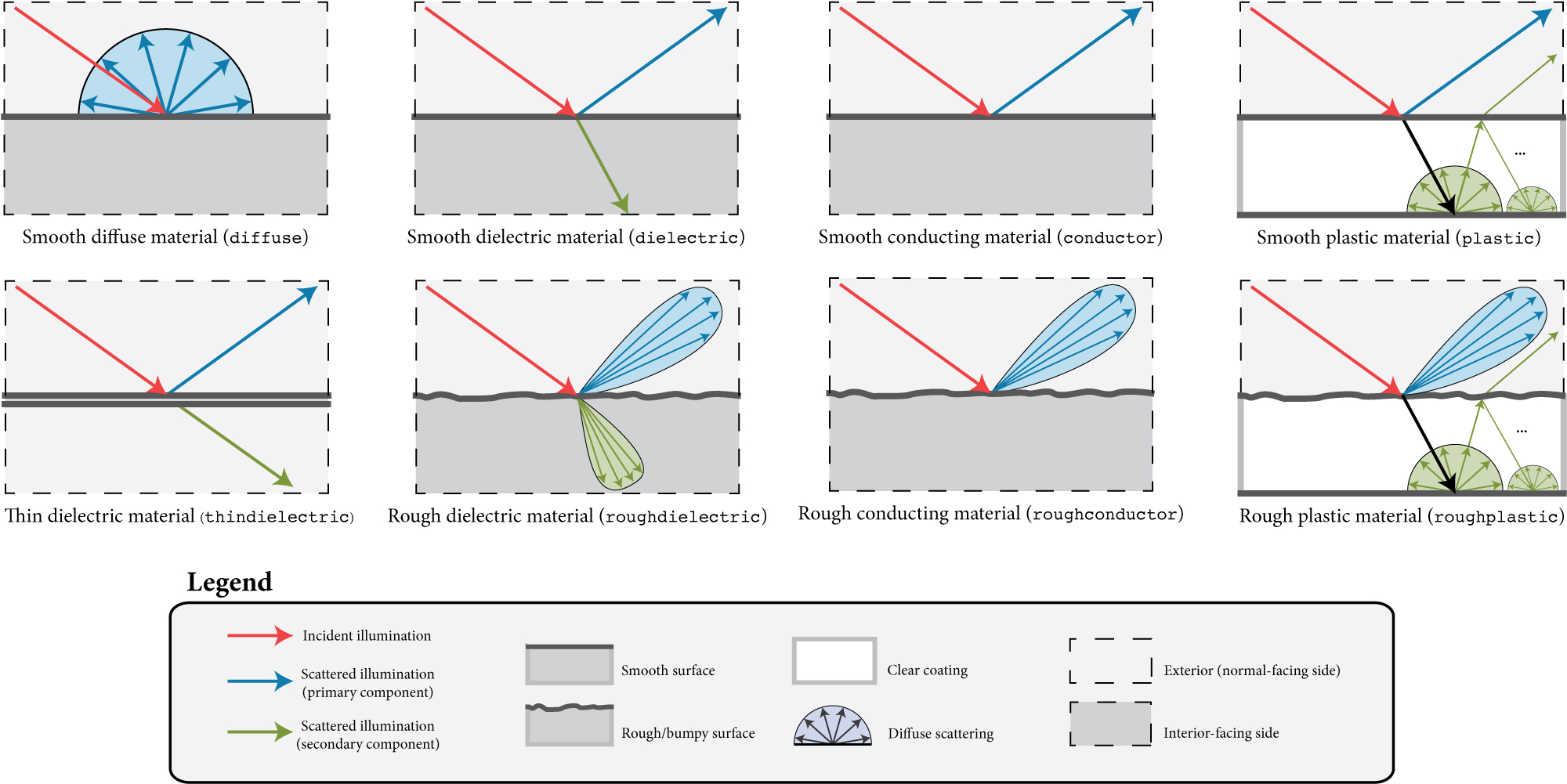
Schematic overview of the most important surface scattering models in Mitsuba 3. The arrows indicate possible outcomes of an interaction with a surface that has the respective model applied to it.
Surface scattering models describe the manner in which light interacts with surfaces in the scene. They conveniently summarize the mesoscopic scattering processes that take place within the material and cause it to look the way it does. This represents one central component of the material system in Mitsuba 3—another part of the renderer concerns itself with what happens in between surface interactions. For more information on this aspect, please refer to the sections regarding participating media. This section presents an overview of all surface scattering models that are supported, along with their parameters.
To achieve realistic results, Mitsuba 3 comes with a library of general-purpose surface scattering models such as glass, metal, or plastic. Some model plugins can also act as modifiers that are applied on top of one or more scattering models.
Throughout the documentation and within the scene description language, the word BSDF is used synonymously with the term surface scattering model. This is an abbreviation for Bidirectional Scattering Distribution Function, a more precise technical term.
In Mitsuba 3, BSDFs are assigned to shapes, which describe the visible surfaces in the scene. In the scene description language, this assignment can either be performed by nesting BSDFs within shapes, or they can be named and then later referenced by their name. The following fragment shows an example of both kinds of usages:
<scene version="3.0.0">
    <!-- Creating a named BSDF for later use -->
    <bsdf type=".. BSDF type .." id="my_named_material">
        <!-- BSDF parameters go here -->
    </bsdf>

    <shape type="sphere">
        <!-- Example of referencing a named material -->
        <ref id="my_named_material"/>
    </shape>

    <shape type="sphere">
        <!-- Example of instantiating an unnamed material -->
        <bsdf type=".. BSDF type ..">
            <!-- BSDF parameters go here -->
        </bsdf>
    </shape>
</scene>
'type': 'scene',
# Create a named BSDF for later use
'my_named_material': {
    'type': '<bsdf_type>',
    # ...
},

'shape_id_0': {
    # Example of referencing a named material
    'bsdf' : {
        'type' : 'ref',
        'id' : 'my_named_material'
    }
},

'shape_id_1': {
    # Example of instantiating an unnamed material
    'bsdf' : {
       'type': '<bsdf_type>',
       # ...
    }
}
It is generally more economical to use named BSDFs when they are used in several places, since this reduces the internal memory usage.
Correctness considerations
A vital consideration when modeling a scene in a physically-based rendering system is that the used materials do not violate physical properties, and that their arrangement is meaningful. For instance, imagine having designed an architectural interior scene that looks good except for a white desk that seems a bit too dark. A closer inspection reveals that it uses a Lambertian material with a diffuse reflectance of 0.9.
In many rendering systems, it would be feasible to increase the reflectance value above 1.0 in such a situation. But in Mitsuba, even a small surface that reflects a little more light than it receives will likely break the available rendering algorithms, or cause them to produce otherwise unpredictable results. In fact, the right solution in this case would be to switch to a different lighting setup that causes more illumination to be received by the desk and then reduce the material’s reflectance—after all, it is quite unlikely that one could find a real-world desk that reflects 90% of all incident light.
As another example of the necessity for a meaningful material description, consider the glass model illustrated in the figure below. Here, careful thinking is needed to decompose the object into boundaries that mark index of refraction-changes. If this is done incorrectly and a beam of light can potentially pass through a sequence of incompatible index of refraction changes (e.g. 1.00 to 1.33 followed by 1.50 to 1.33), the output is undefined and will quite likely even contain inaccuracies in parts of the scene that are far away from the glass.

Some of the scattering models in Mitsuba need to know the indices of refraction on the exterior and interior-facing side of a surface. It is therefore important to decompose the mesh into meaningful separate surfaces corresponding to each index of refraction change. The example here shows such a decomposition for a water-filled glass.
Smooth diffuse material (diffuse)
Parameter |
Type |
Description |
Flags |
|---|---|---|---|
reflectance |
spectrum or texture |
Specifies the diffuse albedo of the material (Default: 0.5) |
P, ∂ |
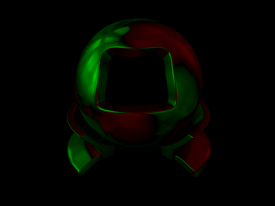
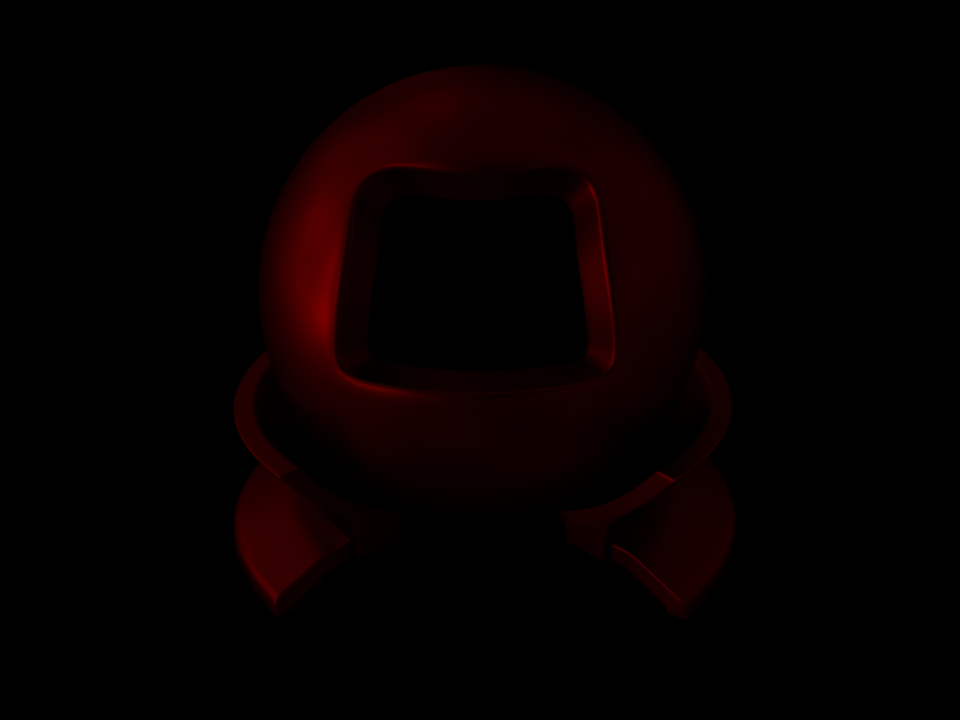
The smooth diffuse material (also referred to as Lambertian) represents an ideally diffuse material with a user-specified amount of reflectance. Any received illumination is scattered so that the surface looks the same independently of the direction of observation.
Apart from a homogeneous reflectance value, the plugin can also accept a nested or referenced texture map to be used as the source of reflectance information, which is then mapped onto the shape based on its UV parameterization. When no parameters are specified, the model uses the default of 50% reflectance.
Note that this material is one-sided—that is, observed from the back side, it will be completely black. If this is undesirable, consider using the twosided BRDF adapter plugin. The following XML snippet describes a diffuse material, whose reflectance is specified as an sRGB color:
<bsdf type="diffuse">
    <rgb name="reflectance" value="0.2, 0.25, 0.7"/>
</bsdf>
'type': 'diffuse',
'reflectance': {
    'type': 'rgb',
    'value': [0.2, 0.25, 0.7]
}
Alternatively, the reflectance can be textured:
<bsdf type="diffuse">
    <texture type="bitmap" name="reflectance">
        <string name="filename" value="wood.jpg"/>
    </texture>
</bsdf>
'type': 'diffuse',
'reflectance': {
    'type': 'bitmap',
    'filename': 'wood.jpg'
}
Smooth dielectric material (dielectric)
Parameter |
Type |
Description |
Flags |
|---|---|---|---|
int_ior |
float or string |
Interior index of refraction specified numerically or using a known material name. (Default: bk7 / 1.5046) |
|
ext_ior |
float or string |
Exterior index of refraction specified numerically or using a known material name. (Default: air / 1.000277) |
|
specular_reflectance |
spectrum or texture |
Optional factor that can be used to modulate the specular reflection component. Note that for physical realism, this parameter should never be touched. (Default: 1.0) |
P, ∂ |
specular_transmittance |
spectrum or texture |
Optional factor that can be used to modulate the specular transmission component. Note that for physical realism, this parameter should never be touched. (Default: 1.0) |
P, ∂ |
State parameters |
|||
eta |
float |
Relative index of refraction from the exterior to the interior |
P |
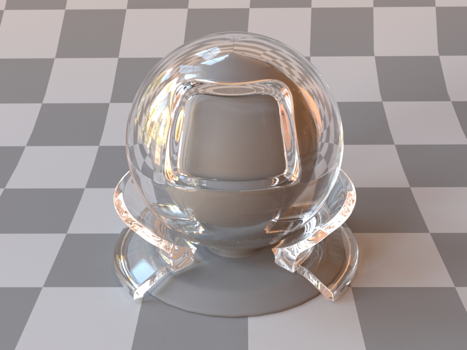
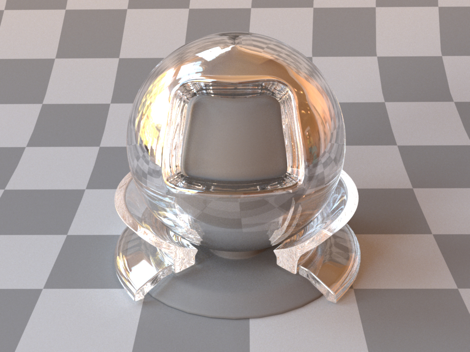
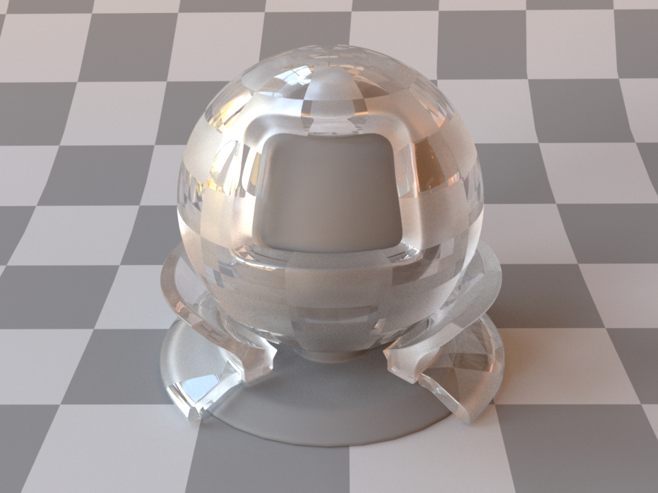
This plugin models an interface between two dielectric materials having mismatched indices of refraction (for instance, water ↔ air). Exterior and interior IOR values can be specified independently, where “exterior” refers to the side that contains the surface normal. When no parameters are given, the plugin activates the defaults, which describe a borosilicate glass (BK7) ↔ air interface.
In this model, the microscopic structure of the surface is assumed to be perfectly smooth, resulting in a degenerate BSDF described by a Dirac delta distribution. This means that for any given incoming ray of light, the model always scatters into a discrete set of directions, as opposed to a continuum. For a similar model that instead describes a rough surface microstructure, take a look at the roughdielectric plugin.
This snippet describes a simple air-to-water interface
<shape type="...">
    <bsdf type="dielectric">
        <string name="int_ior" value="water"/>
        <string name="ext_ior" value="air"/>
    </bsdf>
</shape>
'type': 'dielectric',
'int_ior': 'water',
'ext_ior': 'air'
When using this model, it is crucial that the scene contains meaningful and mutually compatible indices of refraction changes—see the section about correctness considerations for a description of what this entails.
In many cases, we will want to additionally describe the medium within a dielectric material. This requires the use of a rendering technique that is aware of media (e.g. the volumetric path tracer). An example of how one might describe a slightly absorbing piece of glass is shown below:
<shape type="...">
    <bsdf type="dielectric">
        <float name="int_ior" value="1.504"/>
        <float name="ext_ior" value="1.0"/>
    </bsdf>

    <medium type="homogeneous" name="interior">
        <float name="scale" value="4"/>
        <rgb name="sigma_t" value="1, 1, 0.5"/>
        <rgb name="albedo" value="0.0, 0.0, 0.0"/>
    </medium>
</shape>
'type': '...',
'glass':  {
    'type': 'dielectric',
    'int_ior': 1.504,
    'ext_ior': 1.0
},
'interior': {
    'type': 'homogeneous',
    'scale': 4,
    'sigma_t': {
        'type': 'rgb',
        'value': [1, 1, 0.5]
    },
    'albedo': {
        'type': 'rgb',
        'value': [0.0, 0.0, 0.0]
    }
}
In polarized rendering modes, the material automatically switches to a polarized implementation of the underlying Fresnel equations that quantify the reflectance and transmission.
Instead of specifying numerical values for the indices of refraction, Mitsuba 3 comes with a list of presets that can be specified with the material parameter:
Name |
Value |
Name |
Value |
|---|---|---|---|
vacuum |
1.0 |
acetone |
1.36 |
bromine |
1.661 |
bk7 |
1.5046 |
helium |
1.00004 |
ethanol |
1.361 |
water ice |
1.31 |
sodium chloride |
1.544 |
hydrogen |
1.00013 |
carbon tetrachloride |
1.461 |
fused quartz |
1.458 |
amber |
1.55 |
air |
1.00028 |
glycerol |
1.4729 |
pyrex |
1.470 |
pet |
1.575 |
carbon dioxide |
1.00045 |
benzene |
1.501 |
acrylic glass |
1.49 |
diamond |
2.419 |
water |
1.3330 |
silicone oil |
1.52045 |
polypropylene |
1.49 |
This table lists all supported material names along with along with their associated index of refraction at standard conditions. These material names can be used with the plugins dielectric, roughdielectric, plastic , as well as roughplastic.
Thin dielectric material (thindielectric)
Parameter |
Type |
Description |
Flags |
|---|---|---|---|
int_ior |
float or string |
Interior index of refraction specified numerically or using a known material name. (Default: bk7 / 1.5046) |
|
ext_ior |
float or string |
Exterior index of refraction specified numerically or using a known material name. (Default: air / 1.000277) |
|
specular_reflectance |
spectrum or texture |
Optional factor that can be used to modulate the specular reflection component. Note that for physical realism, this parameter should never be touched. (Default: 1.0) |
P, ∂ |
specular_transmittance |
spectrum or texture |
Optional factor that can be used to modulate the specular transmission component. Note that for physical realism, this parameter should never be touched. (Default: 1.0) |
P, ∂ |
State parameters |
|||
eta |
float |
Relative index of refraction from the exterior to the interior |
P, ∂, D |
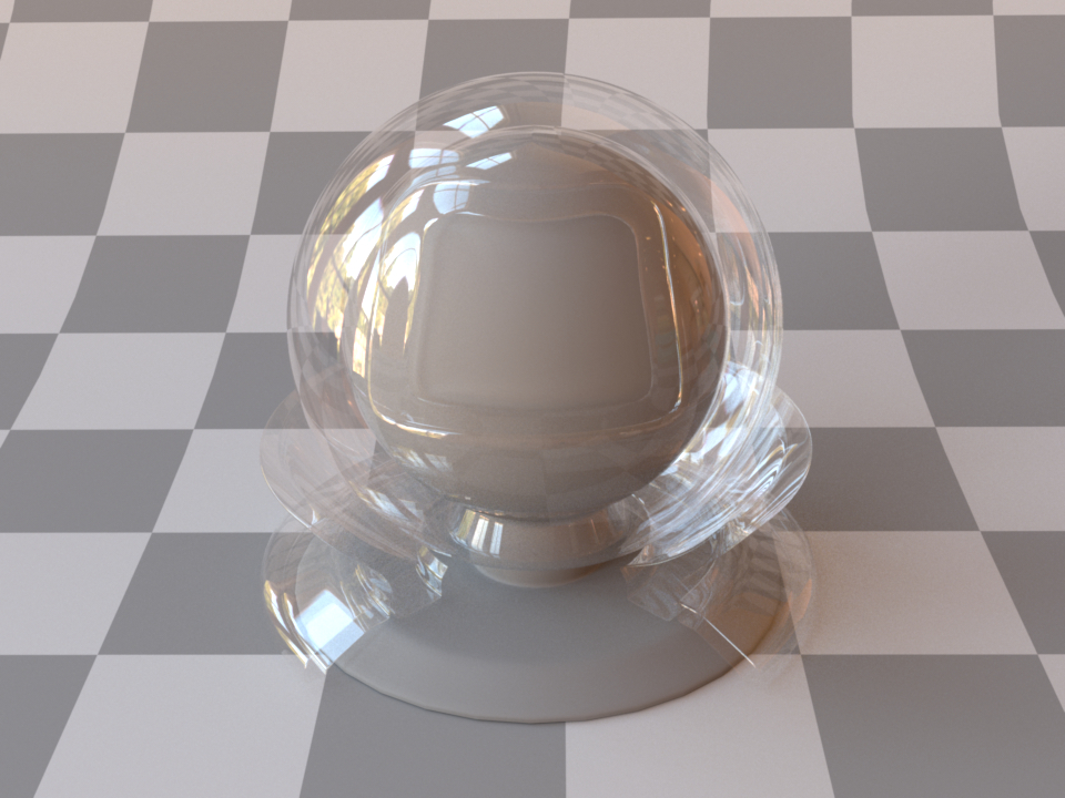
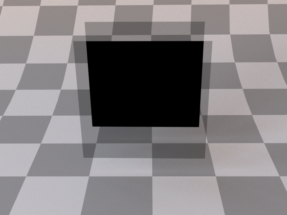
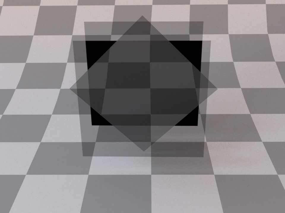
This plugin models a thin dielectric material that is embedded inside another dielectric—for instance, glass surrounded by air. The interior of the material is assumed to be so thin that its effect on transmitted rays is negligible, Hence, light exits such a material without any form of angular deflection (though there is still specular reflection). This model should be used for things like glass windows that were modeled using only a single sheet of triangles or quads. On the other hand, when the window consists of proper closed geometry, dielectric is the right choice. This is illustrated below:

The dielectric plugin models a single transition from one index of refraction to another

The thindielectric plugin models a pair of interfaces causing a transient index of refraction change
The implementation correctly accounts for multiple internal reflections inside the thin dielectric at no significant extra cost, i.e. paths of the type \(R, TRT, TR^3T, ..\) for reflection and \(TT, TR^2, TR^4T, ..\) for refraction, where \(T\) and \(R\) denote individual reflection and refraction events, respectively.
Similar to the dielectric plugin, IOR values can either be specified numerically, or based on a list of known materials (see the corresponding table in the dielectric reference). When no parameters are given, the plugin activates the default settings, which describe a borosilicate glass (BK7) ↔ air interface.
<bsdf type="thindielectric">
    <string name="int_ior" value="bk7"/>
    <string name="ext_ior" value="air"/>
</bsdf>
'type': 'thindielectric',
'int_ior': 'bk7',
'ext_ior': 'air'
Warning
This BSDF does not have support for polarized variants.
Rough dielectric material (roughdielectric)
Parameter |
Type |
Description |
Flags |
|---|---|---|---|
int_ior |
float or string |
Interior index of refraction specified numerically or using a known material name. (Default: bk7 / 1.5046) |
|
ext_ior |
float or string |
Exterior index of refraction specified numerically or using a known material name. (Default: air / 1.000277) |
|
specular_reflectance, specular_transmittance |
spectrum or texture |
Optional factor that can be used to modulate the specular reflection/transmission components. Note that for physical realism, these parameters should never be touched. (Default: 1.0) |
P, ∂ |
distribution |
string |
Specifies the type of microfacet normal distribution used to model the surface roughness.
|
|
alpha, alpha_u, alpha_v |
texture or float |
Specifies the roughness of the unresolved surface micro-geometry along the tangent and bitangent directions. When the Beckmann distribution is used, this parameter is equal to the root mean square (RMS) slope of the microfacets. alpha is a convenience parameter to initialize both alpha_u and alpha_v to the same value. (Default: 0.1) |
P, ∂, D |
sample_visible |
boolean |
Enables a sampling technique proposed by Heitz and D’Eon [HDEon14], which focuses computation on the visible parts of the microfacet normal distribution, considerably reducing variance in some cases. (Default: true, i.e. use visible normal sampling) |
|
State parameters |
|||
eta |
float |
Relative index of refraction from the exterior to the interior |
P, ∂, D |
This plugin implements a realistic microfacet scattering model for rendering rough interfaces between dielectric materials, such as a transition from air to ground glass. Microfacet theory describes rough surfaces as an arrangement of unresolved and ideally specular facets, whose normal directions are given by a specially chosen microfacet distribution. By accounting for shadowing and masking effects between these facets, it is possible to reproduce the important off-specular reflections peaks observed in real-world measurements of such materials.
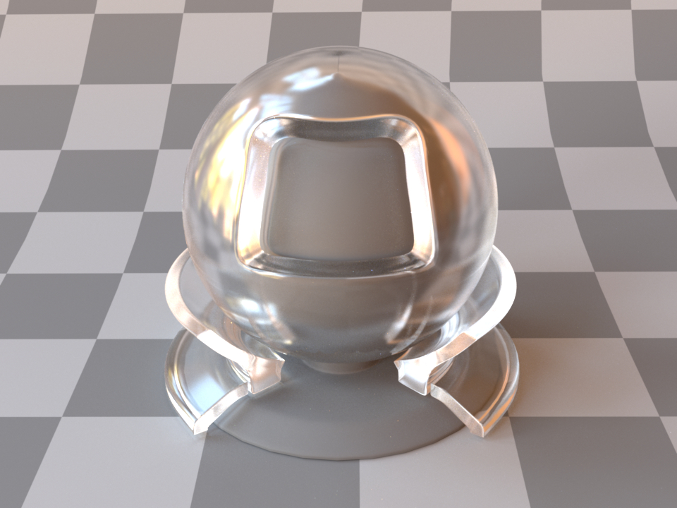
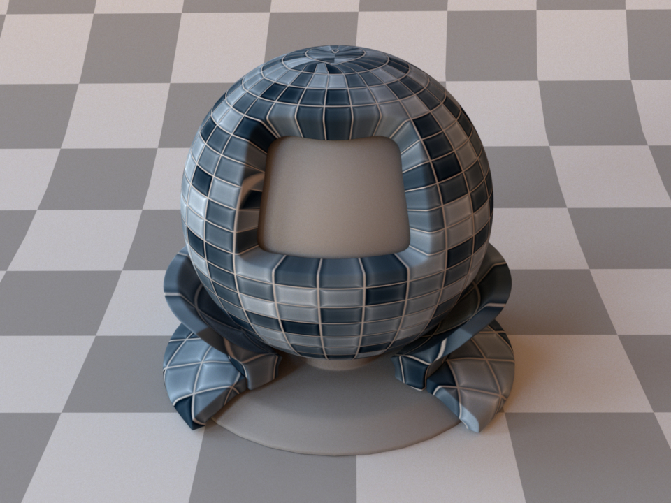
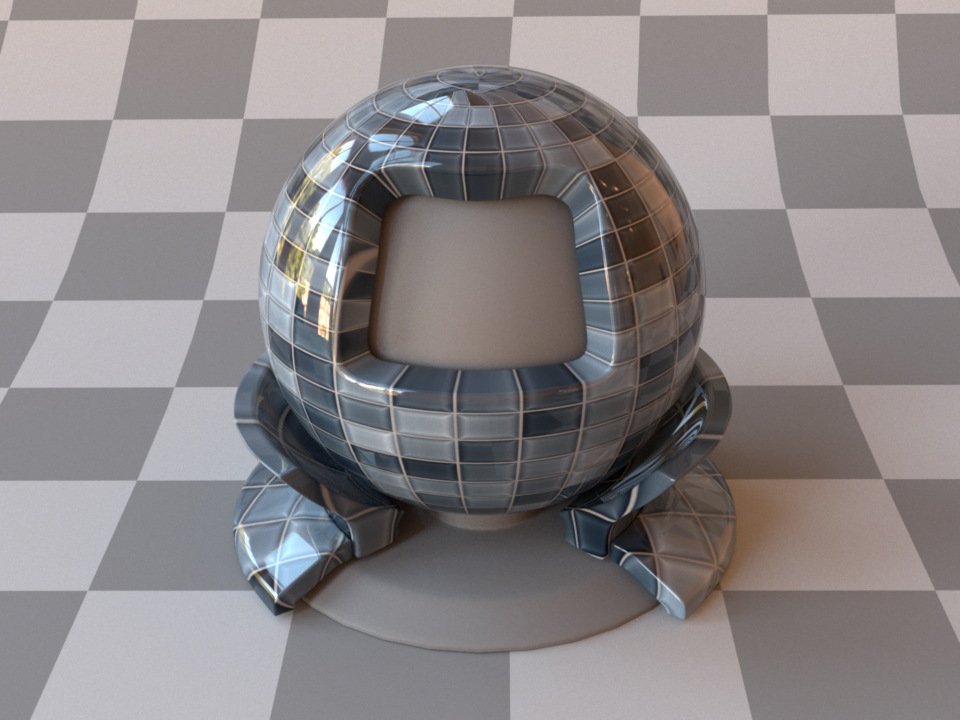
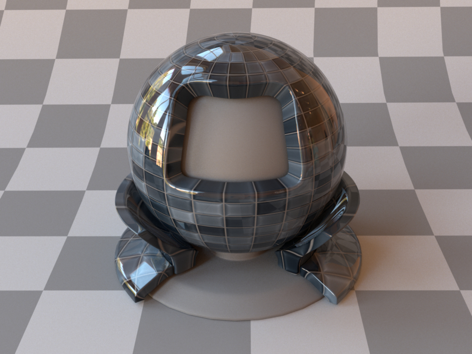
Anti-glare glass (Beckmann, \(\alpha=0.02\))
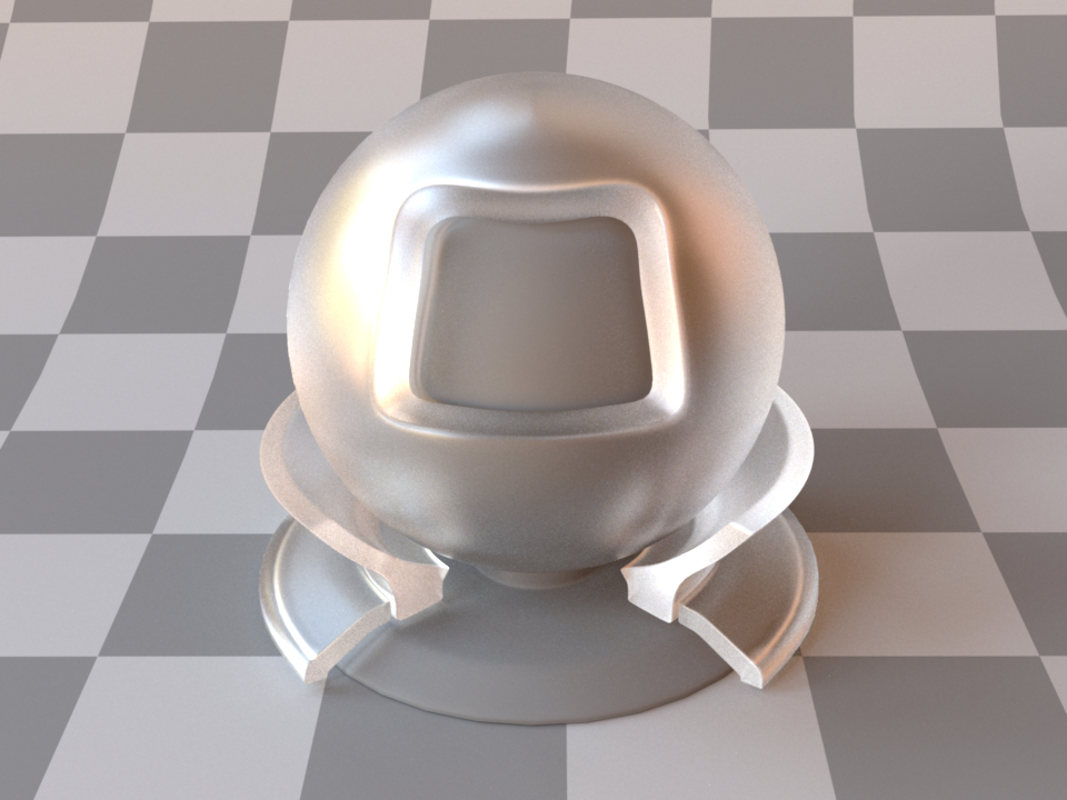
Rough glass (Beckmann, \(\alpha=0.1\))
Rough glass with textured alpha
This plugin is essentially the roughened equivalent of the (smooth) plugin dielectric. For very low values of \(\alpha\), the two will be identical, though scenes using this plugin will take longer to render due to the additional computational burden of tracking surface roughness.
The implementation is based on the paper Microfacet Models for Refraction through Rough Surfaces by Walter et al. [WMLT07] and supports two different types of microfacet distributions. Exterior and interior IOR values can be specified independently, where exterior refers to the side that contains the surface normal. Similar to the dielectric plugin, IOR values can either be specified numerically, or based on a list of known materials (see the corresponding table in the dielectric reference). When no parameters are given, the plugin activates the default settings, which describe a borosilicate glass (BK7) ↔ air interface with a light amount of roughness modeled using a Beckmann distribution.
To get an intuition about the effect of the surface roughness parameter \(\alpha\), consider the following approximate classification: a value of \(\alpha=0.001-0.01\) corresponds to a material with slight imperfections on an otherwise smooth surface finish, \(\alpha=0.1\) is relatively rough, and \(\alpha=0.3-0.7\) is extremely rough (e.g. an etched or ground finish). Values significantly above that are probably not too realistic.
Please note that when using this plugin, it is crucial that the scene contains meaningful and mutually compatible index of refraction changes—see the section about correctness considerations for a description of what this entails.
Warning
This BSDF does not have support for polarized variants.
The following XML snippet describes a material definition for rough glass:
<bsdf type="roughdielectric">
    <string name="distribution" value="beckmann"/>
    <float name="alpha" value="0.1"/>
    <string name="int_ior" value="bk7"/>
    <string name="ext_ior" value="air"/>
</bsdf>
'type': 'roughdielectric',
'distribution': 'beckmann',
'alpha': 0.1,
'int_ior': 'bk7',
'ext_ior': 'air'
Technical details
All microfacet distributions allow the specification of two distinct roughness values along the tangent and bitangent directions. This can be used to provide a material with a brushed appearance. The alignment of the anisotropy will follow the UV parameterization of the underlying mesh. This means that such an anisotropic material cannot be applied to triangle meshes that are missing texture coordinates.
Since Mitsuba 0.5.1, this plugin uses a new importance sampling technique contributed by Eric Heitz and Eugene D’Eon, which restricts the sampling domain to the set of visible (unmasked) microfacet normals. The previous approach of sampling all normals is still available and can be enabled by setting sample_visible to false. However this will lead to significantly slower convergence.
Smooth conductor (conductor)
Parameter |
Type |
Description |
Flags |
|---|---|---|---|
material |
string |
Name of the material preset, see conductor-ior-list. (Default: none) |
|
eta, k |
spectrum or texture |
Real and imaginary components of the material’s index of refraction. (Default: based on the value of material) |
P, ∂, D |
specular_reflectance |
spectrum or texture |
Optional factor that can be used to modulate the specular reflection component. Note that for physical realism, this parameter should never be touched. (Default: 1.0) |
P, ∂ |
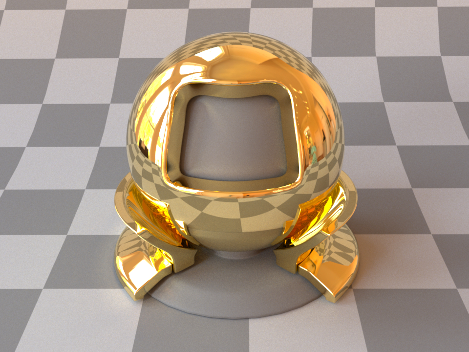
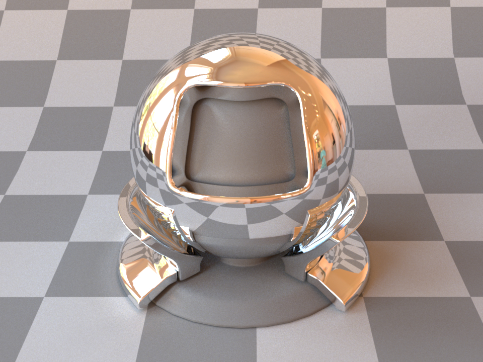
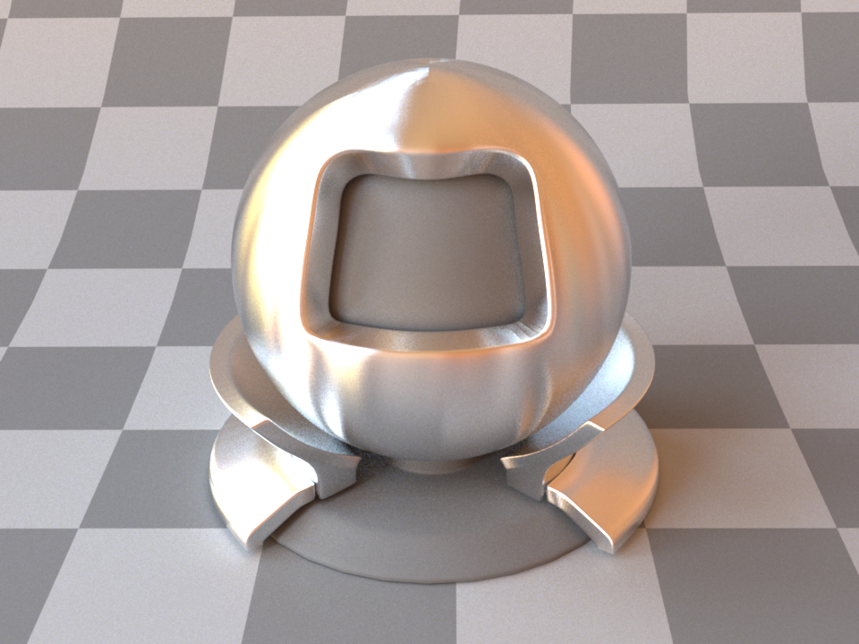
This plugin implements a perfectly smooth interface to a conducting material, such as a metal that is described using a Dirac delta distribution. For a similar model that instead describes a rough surface microstructure, take a look at the separately available roughconductor plugin. In contrast to dielectric materials, conductors do not transmit any light. Their index of refraction is complex-valued and tends to undergo considerable changes throughout the visible color spectrum.
When using this plugin, you should ideally enable one of the spectral modes of the renderer to get the most accurate results. While it also works in RGB mode, the computations will be more approximate in nature. Also note that this material is one-sided—that is, observed from the back side, it will be completely black. If this is undesirable, consider using the twosided BRDF adapter plugin.
The following XML snippet describes a material definition for gold:
<bsdf type="conductor">
    <string name="material" value="Au"/>
</bsdf>
'type': 'conductor',
'material': 'Au'
It is also possible to load spectrally varying index of refraction data from two external files containing the real and imaginary components, respectively (see Scene format for details on the file format):
<bsdf type="conductor">
    <spectrum name="eta" filename="conductorIOR.eta.spd"/>
    <spectrum name="k" filename="conductorIOR.k.spd"/>
</bsdf>
'type': 'conductor',
'eta':  {
    'type': 'spectrum',
    'filename': 'conductorIOR.eta.spd'
},
'k':  {
    'type': 'spectrum',
    'filename': 'conductorIOR.k.spd'
}
In polarized rendering modes, the material automatically switches to a polarized implementation of the underlying Fresnel equations.
To facilitate the tedious task of specifying spectrally-varying index of refraction information, Mitsuba 3 ships with a set of measured data for several materials, where visible-spectrum information was publicly available:
Preset(s) |
Description |
Preset(s) |
Description |
|---|---|---|---|
a-C |
Amorphous carbon |
Na_palik |
Sodium |
Ag |
Silver |
Nb, Nb_palik |
Niobium |
Al |
Aluminium |
Ni_palik |
Nickel |
AlAs, AlAs_palik |
Cubic aluminium arsenide |
Rh, Rh_palik |
Rhodium |
AlSb, AlSb_palik |
Cubic aluminium antimonide |
Se, Se_palik |
Selenium |
Au |
Gold |
SiC, SiC_palik |
Hexagonal silicon carbide |
Be, Be_palik |
Polycrystalline beryllium |
SnTe, SnTe_palik |
Tin telluride |
Cr |
Chromium |
Ta, Ta_palik |
Tantalum |
CsI, CsI_palik |
Cubic caesium iodide |
Te, Te_palik |
Trigonal tellurium |
Cu, Cu_palik |
Copper |
ThF4, ThF4_palik |
Polycryst. thorium (IV) fluoride |
Cu2O, Cu2O_palik |
Copper (I) oxide |
TiC, TiC_palik |
Polycrystalline titanium carbide |
CuO, CuO_palik |
Copper (II) oxide |
TiN, TiN_palik |
Titanium nitride |
d-C, d-C_palik |
Cubic diamond |
TiO2, TiO2_palik |
Tetragonal titan. dioxide |
Hg, Hg_palik |
Mercury |
VC, VC_palik |
Vanadium carbide |
HgTe, HgTe_palik |
Mercury telluride |
V_palik |
Vanadium |
Ir, Ir_palik |
Iridium |
VN, VN_palik |
Vanadium nitride |
K, K_palik |
Polycrystalline potassium |
W |
Tungsten |
Li, Li_palik |
Lithium |
||
MgO, MgO_palik |
Magnesium oxide |
||
Mo, Mo_palik |
Molybdenum |
none |
No mat. profile (100% reflecting mirror) |
This table lists all supported materials that can be passed into the conductor and roughconductor plugins. Note that some of them are not actually conductors—this is not a problem, they can be used regardless (though only the reflection component and no transmission will be simulated). In most cases, there are multiple entries for each material, which represent measurements by different authors.
These index of refraction values are identical to the data distributed with PBRT. They are originally from the Luxpop database and are based on data by Palik et al. [PG98] and measurements of atomic scattering factors made by the Center For X-Ray Optics (CXRO) at Berkeley and the Lawrence Livermore National Laboratory (LLNL).
There is also a special material profile named none, which disables the computation of Fresnel reflectances and produces an idealized 100% reflecting mirror.
Rough conductor material (roughconductor)
Parameter |
Type |
Description |
Flags |
|---|---|---|---|
material |
string |
Name of the material preset, see conductor-ior-list. (Default: none) |
|
eta, k |
spectrum or texture |
Real and imaginary components of the material’s index of refraction. (Default: based on the value of material) |
P, ∂, D |
specular_reflectance |
spectrum or texture |
Optional factor that can be used to modulate the specular reflection component. Note that for physical realism, this parameter should never be touched. (Default: 1.0) |
P, ∂ |
distribution |
string |
Specifies the type of microfacet normal distribution used to model the surface roughness.
|
|
alpha, alpha_u, alpha_v |
texture or float |
Specifies the roughness of the unresolved surface micro-geometry along the tangent and bitangent directions. When the Beckmann distribution is used, this parameter is equal to the root mean square (RMS) slope of the microfacets. alpha is a convenience parameter to initialize both alpha_u and alpha_v to the same value. (Default: 0.1) |
P, ∂, D |
sample_visible |
boolean |
Enables a sampling technique proposed by Heitz and D’Eon [HDEon14], which focuses computation on the visible parts of the microfacet normal distribution, considerably reducing variance in some cases. (Default: true, i.e. use visible normal sampling) |
This plugin implements a realistic microfacet scattering model for rendering rough conducting materials, such as metals.
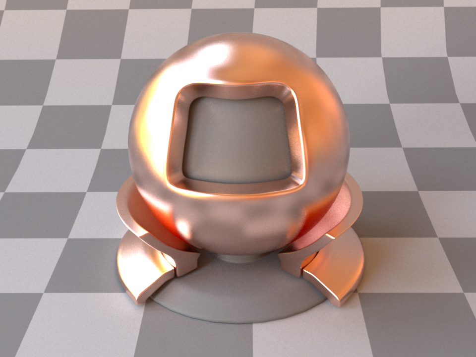
Rough copper (Beckmann, \(\alpha=0.1\))
Vertically brushed aluminium (Anisotropic Beckmann, \(\alpha_u=0.05,\ \alpha_v=0.3\))
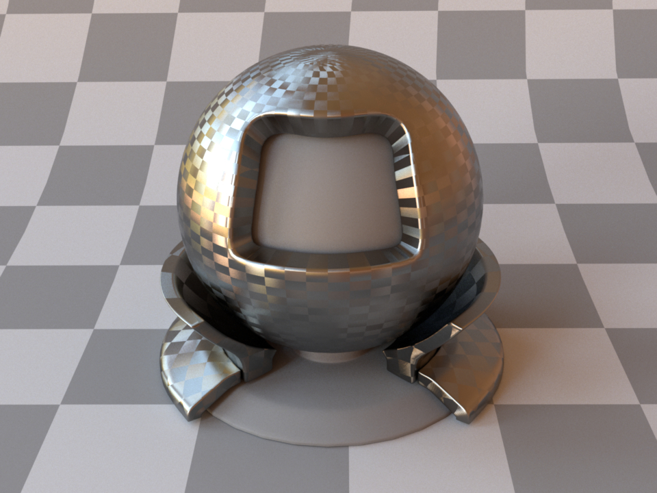
Carbon fiber using two inverted checkerboard textures for alpha_u and alpha_v
Microfacet theory describes rough surfaces as an arrangement of unresolved and ideally specular facets, whose normal directions are given by a specially chosen microfacet distribution. By accounting for shadowing and masking effects between these facets, it is possible to reproduce the important off-specular reflections peaks observed in real-world measurements of such materials.
This plugin is essentially the roughened equivalent of the (smooth) plugin conductor. For very low values of \(\alpha\), the two will be identical, though scenes using this plugin will take longer to render due to the additional computational burden of tracking surface roughness.
The implementation is based on the paper Microfacet Models for Refraction through Rough Surfaces by Walter et al. [WMLT07] and it supports two different types of microfacet distributions.
To facilitate the tedious task of specifying spectrally-varying index of refraction information, this plugin can access a set of measured materials for which visible-spectrum information was publicly available (see the corresponding table in the conductor reference).
When no parameters are given, the plugin activates the default settings, which describe a 100% reflective mirror with a medium amount of roughness modeled using a Beckmann distribution.
To get an intuition about the effect of the surface roughness parameter \(\alpha\), consider the following approximate classification: a value of \(\alpha=0.001-0.01\) corresponds to a material with slight imperfections on an otherwise smooth surface finish, \(\alpha=0.1\) is relatively rough, and \(\alpha=0.3-0.7\) is extremely rough (e.g. an etched or ground finish). Values significantly above that are probably not too realistic.
The following XML snippet describes a material definition for brushed aluminium:
<bsdf type="roughconductor">
    <string name="material" value="Al"/>
    <string name="distribution" value="ggx"/>
    <float name="alpha_u" value="0.05"/>
    <float name="alpha_v" value="0.3"/>
</bsdf>
'type': 'roughconductor',
'material': 'Al',
'distribution': 'ggx',
'alpha_u': 0.05,
'alpha_v': 0.3
Technical details
All microfacet distributions allow the specification of two distinct roughness values along the tangent and bitangent directions. This can be used to provide a material with a brushed appearance. The alignment of the anisotropy will follow the UV parameterization of the underlying mesh. This means that such an anisotropic material cannot be applied to triangle meshes that are missing texture coordinates.
Since Mitsuba 0.5.1, this plugin uses a new importance sampling technique contributed by Eric Heitz and Eugene D’Eon, which restricts the sampling domain to the set of visible (unmasked) microfacet normals. The previous approach of sampling all normals is still available and can be enabled by setting sample_visible to false. However this will lead to significantly slower convergence.
When using this plugin, you should ideally compile Mitsuba with support for spectral rendering to get the most accurate results. While it also works in RGB mode, the computations will be more approximate in nature. Also note that this material is one-sided—that is, observed from the back side, it will be completely black. If this is undesirable, consider using the twosided BRDF adapter.
In polarized rendering modes, the material automatically switches to a polarized implementation of the underlying Fresnel equations.
Hair material (hair)
Parameter |
Type |
Description |
Flags |
|---|---|---|---|
eumelanin, pheomelanin |
float |
Concentration of pigments (Default: 1.3 eumelanin and 0.2 pheomelanin) |
P, ∂, D |
sigma_a |
spectrum or texture |
Absorption coefficient in inverse scene units. The absorption can either be specified with pigmentation concentrations or this parameter, not both. |
P, ∂ |
scale |
float |
Optional scale factor that will be applied to the |
P |
int_ior |
float or string |
Interior index of refraction specified numerically or using a known material name. (Default: amber / 1.55f) |
|
ext_ior |
float or string |
Exterior index of refraction specified numerically or using a known material name. (Default: air / 1.000277) |
|
longitudinal_roughness, azimuthal_roughness |
float |
Hair roughness along each dimension (Default: 0.3 for both) |
P, ∂, D |
State parameters |
|||
scale_tilt |
float |
Angle of the scales on the hair w.r.t. to the hair fiber’s surface. The angle is given in degrees. (Default: 2) |
P, ∂, D |
use_pigmentation |
boolean |
Specifies whether to use the pigmentation concentration values or the
absorption coefficient |
P, ∂, D |
eta |
float |
Relative index of refraction from the exterior to the interior |
P, ∂, D |
This plugin is an implementation of the hair model described in the paper A Practical and Controllable Hair and Fur Model for Production Path Tracing by Chiang et al. [CBTB16].
When no parameters are given, the plugin activates the default settings, which describe a brown-ish hair color.
This BSDF is meant to be used with the bsplinecurve shape. Attaching this
material to any other shape might produce unexpected results. This is due to
assumptions about the local geoemtry and frame in the model itself.
This model is considered a “near field” model: the viewer can be close to the hair fibers and observe accurate scattering across the entire fiber. In its implementation, a single scattering event computes the outgoing radiance by assuming no/one/many event(s) inside the fiber and then exiting it. In short, a single interaction encapsulates the entire walk inside fiber. Unintuitively, this also means that the entry and exit point of the walk are exactly the same point on the shape’s geometry.
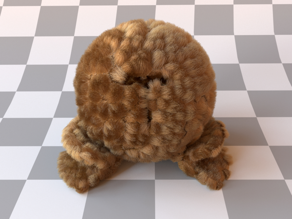
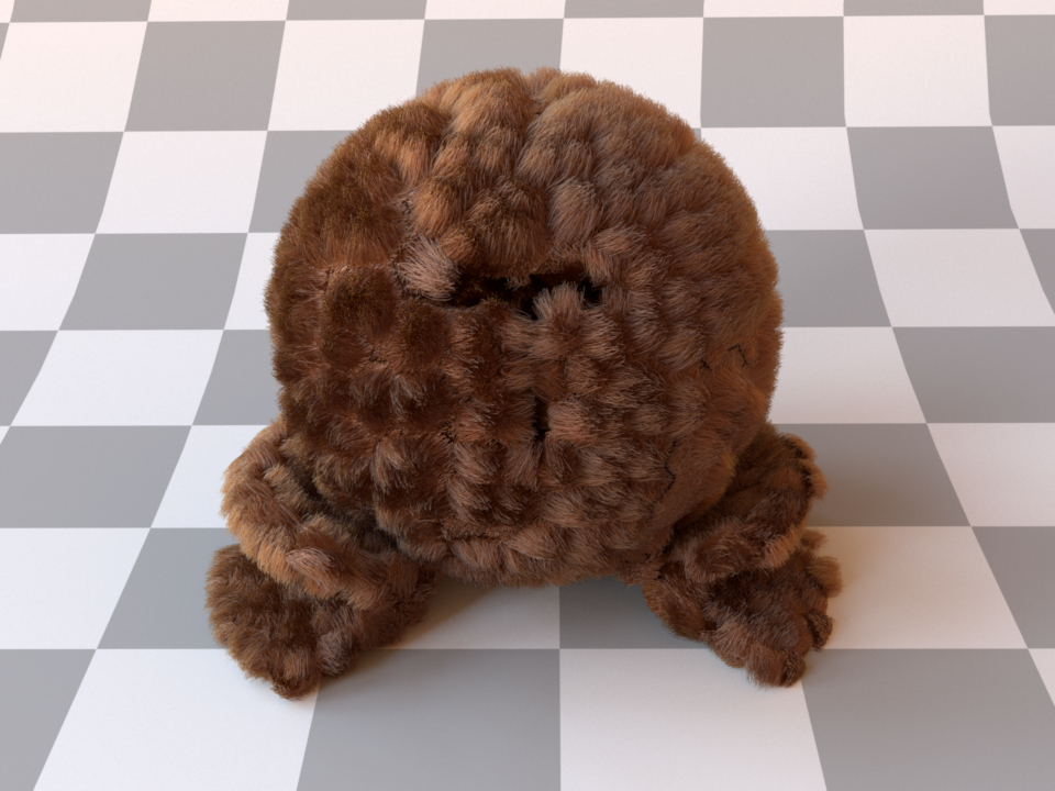
Note
The hair geometry used in the figures above was created by Benedikt Bitterli.
<bsdf type="hair">
    <float name="eumelanin" value="0.2"/>
    <float name="pheomelanin" value="0.4"/>
</bsdf>
'type': 'hair',
'eumelanin': 0.2,
'pheomelanin': 0.4
Alternatively, the absorption coefficient can be specified manually:
<bsdf type="hair">
    <rgb name="sigma_a" value="0.2, 0.25, 0.7"/>
    <float name="scale" value="200"/>
</bsdf>
'type': 'hair',
'sigma_a': {
    'type': 'rgb',
    'value': [0.2, 0.25, 0.7]
},
'scale': 200
Measured material (measured)
Parameter |
Type |
Description |
Flags |
|---|---|---|---|
filename |
string |
Filename of the material data file to be loaded |
This plugin implements the data-driven material model described in the paper An Adaptive Parameterization for Efficient Material Acquisition and Rendering. A database containing compatible materials is are here.
Simply click on a material on this page and then download the RGB or
spectral .bsdf file and pass it to the filename parameter of the
plugin. Note that the spectral data files can only be used in a spectral
variant of Mitsuba, and the RGB-based approximations require an RGB variant.
The original measurements are spectral and cover the 360–1000nm range, hence
it is strongly recommended that you use a spectral workflow. (Many colors
cannot be reliably represented in RGB, as they are outside of the color gamut)
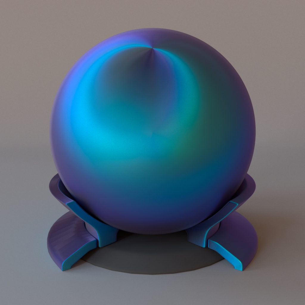
Iridescent butterfly (Dorsal Morpho Melenaus wing, anisotropic)
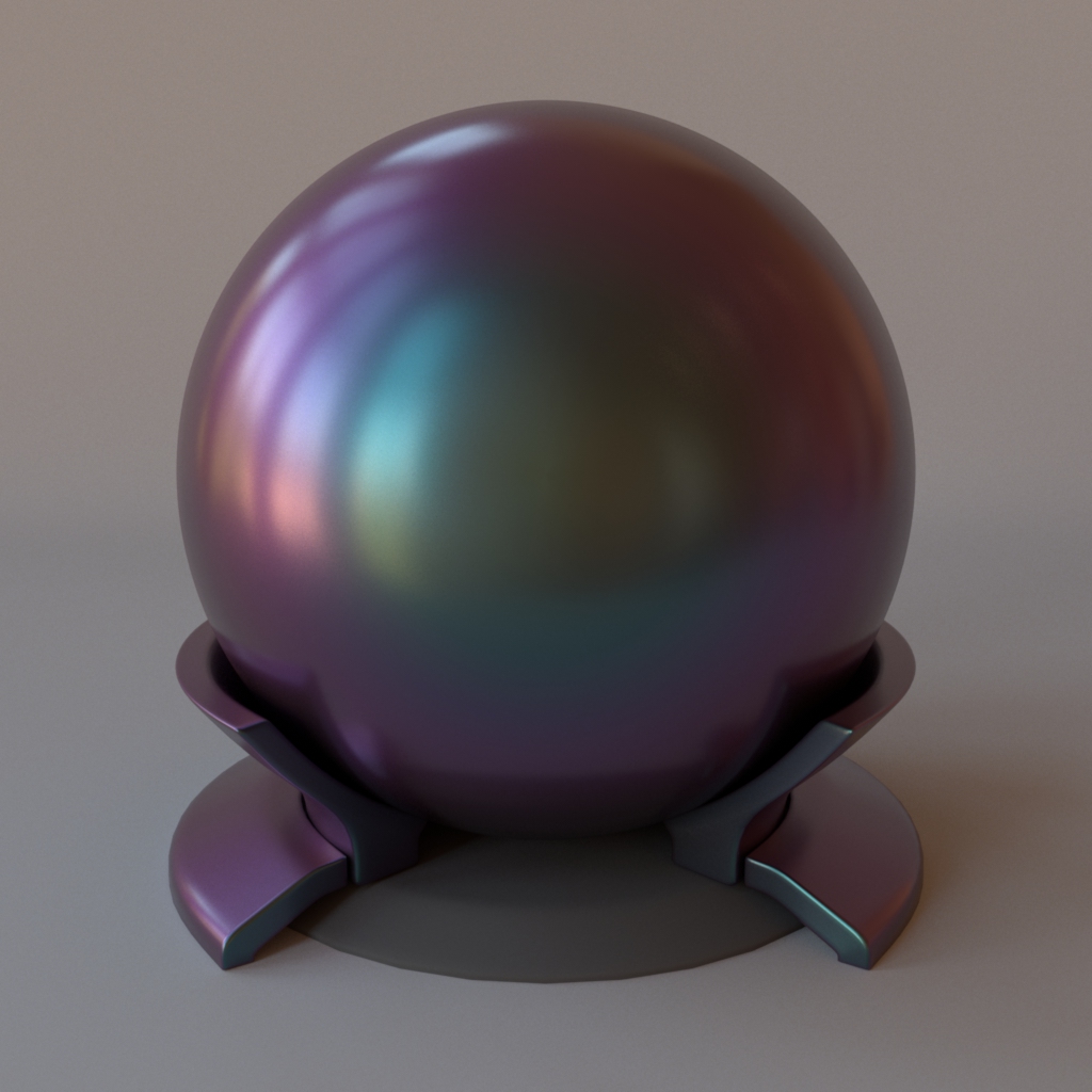
Vinyl car wrap material (TeckWrap RD05 Northern Aurora, isotropic)
Note that this material is one-sided—that is, observed from the back side, it will be completely black. If this is undesirable, consider using the twosided BRDF adapter plugin. The following XML snippet describes how to import one of the spectral measurements from the database.
<bsdf type="measured">
    <string name="filename" value="cc_nothern_aurora_spec.bsdf"/>
</bsdf>
'type': 'measured',
'filename': 'cc_nothern_aurora_spec.bsdf'
Measured polarized material (measured_polarized)
Parameter |
Type |
Description |
Flags |
|---|---|---|---|
filename |
string |
Filename of the material data file to be loaded |
|
alpha_sample |
float |
Specifies which roughness value should be used for the internal Microfacet importance sampling routine. (Default: 0.1) |
|
wavelength |
float |
Specifies if the material should only be rendered for just one specific wavelength. The valid range is between 450 and 650 nm. A value of -1 means the full spectrally-varying pBRDF will be used. (Default: -1, i.e. all wavelengths.) |
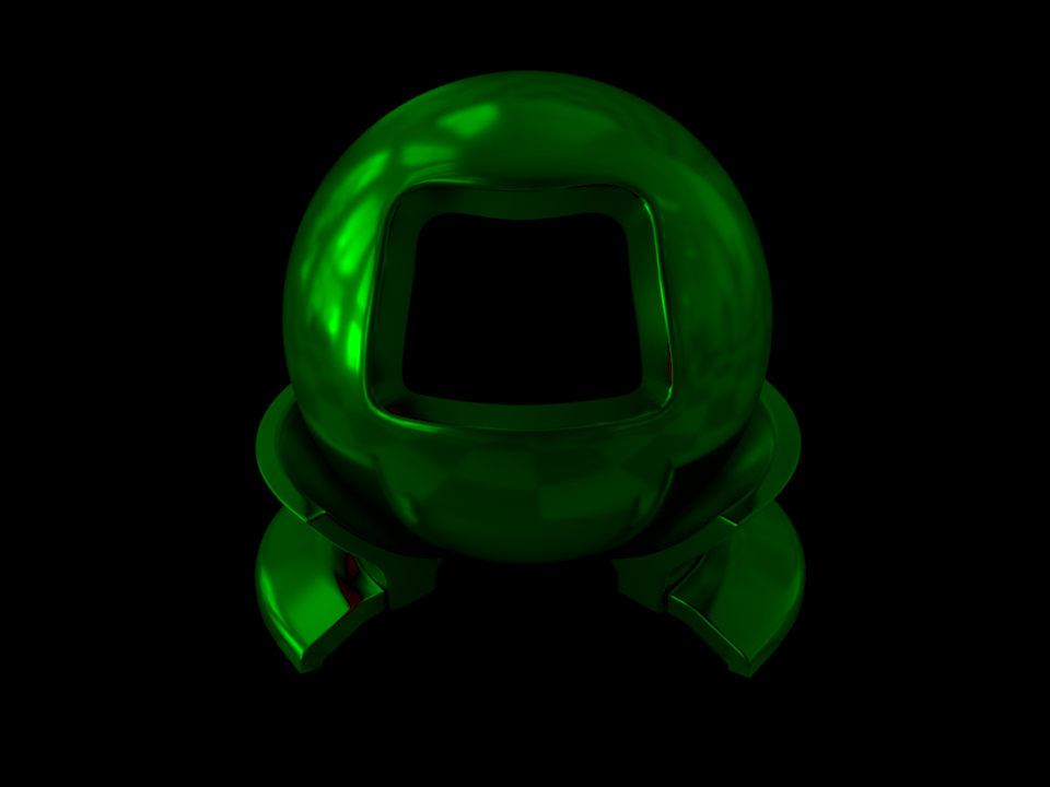
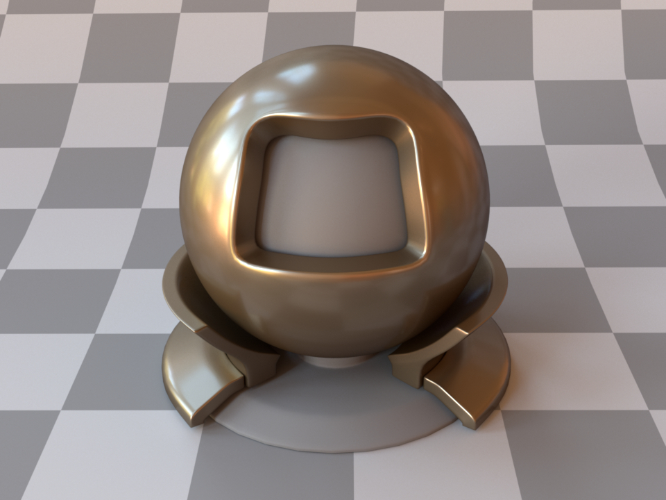
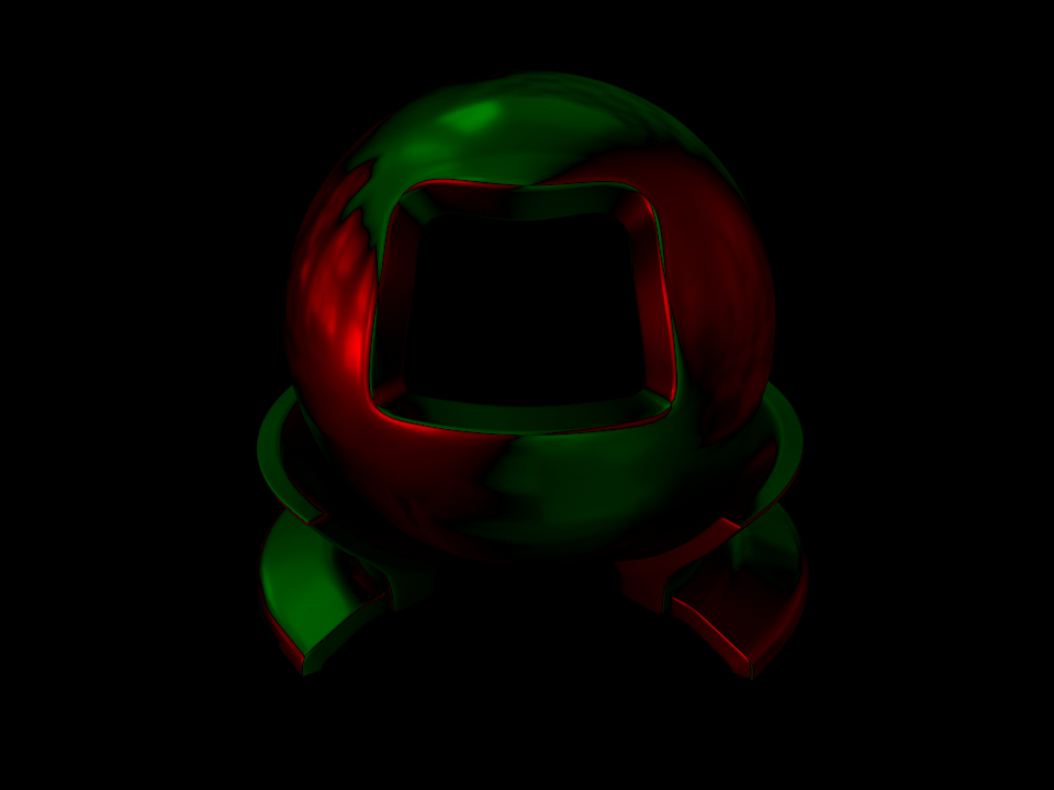
This plugin allows rendering of polarized materials (pBRDFs) acquired as part of “Image-Based Acquisition and Modeling of Polarimetric Reflectance” by Baek et al. 2020 ([BZK+20]). The required files for each material can be found in the corresponding database.
The dataset is made out of isotropic pBRDFs spanning a wide range of appearances: diffuse/specular, metallic/dielectric, rough/smooth, and different color albedos, captured in five wavelength ranges covering the visible spectrum from 450 to 650 nm.
Here are two example materials of gold, and a dielectric “fake” gold, together with visualizations of the resulting Stokes vectors rendered with the Stokes integrator:
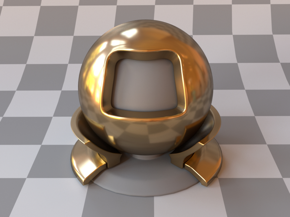
Measured gold material
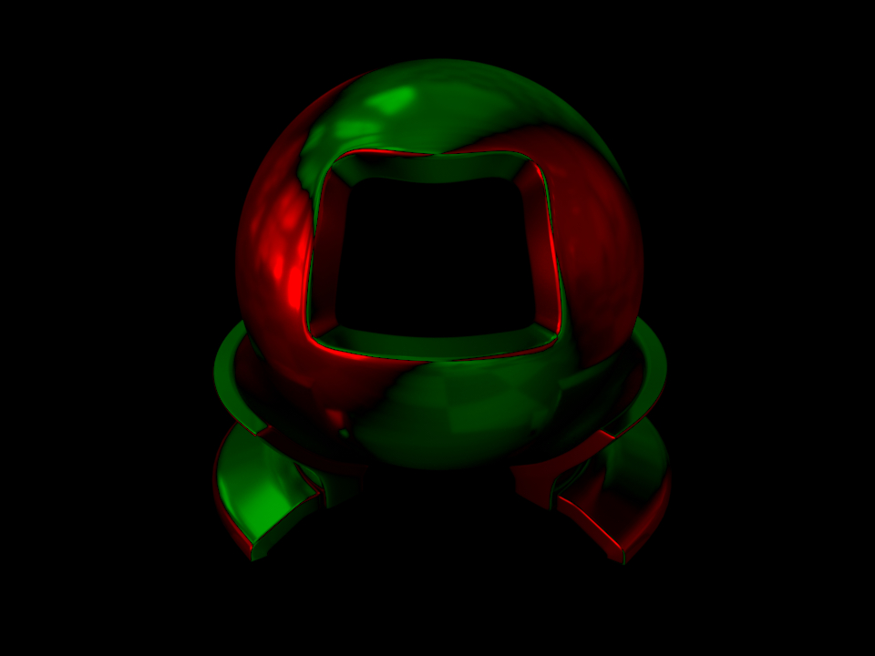
“\(\mathbf{s}_1\)”: horizontal vs. vertical polarization
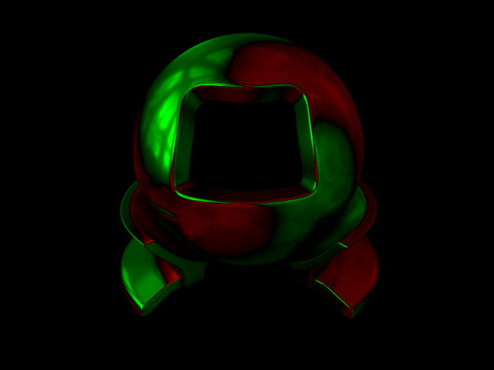
“\(\mathbf{s}_2\)”: positive vs. negative diagonal polarization
“\(\mathbf{s}_3\)”: right vs. left circular polarization
Measured “fake” gold material
“\(\mathbf{s}_1\)”: horizontal vs. vertical polarization
“\(\mathbf{s}_2\)”: positive vs. negative diagonal polarization
“\(\mathbf{s}_3\)”: right vs. left circular polarization
In the following example, the measured gold BSDF from the dataset is setup:
<bsdf type="measured_polarized">
    <string name="filename" value="6_gold_inpainted.pbsdf"/>
    <float name="alpha_sample" value="0.02"/>
</bsdf>
'type': 'measured_polarized',
'filename': '6_gold_inpainted.pbsdf',
'alpha_sample': 0.02
Internally, a sampling routine from the GGX Microfacet model is used in order to
importance sampling outgoing directions. The used GGX roughness value is exposed
here as a user parameter alpha_sample and should be set according to the
approximate roughness of the material to be rendered. Note that any value here
will result in a correct rendering but the level of noise can vary significantly.
Warning
This BSDF is only supported in *_spectral_polarized variants.
Smooth plastic material (plastic)
Parameter |
Type |
Description |
Flags |
|---|---|---|---|
diffuse_reflectance |
spectrum or texture |
Optional factor used to modulate the diffuse reflection component. (Default: 0.5) |
P, ∂ |
nonlinear |
boolean |
Account for nonlinear color shifts due to internal scattering? See the main text for details.. (Default: Don’t account for them and preserve the texture colors, i.e. false) |
|
int_ior |
float or string |
Interior index of refraction specified numerically or using a known material name. (Default: polypropylene / 1.49) |
|
ext_ior |
float or string |
Exterior index of refraction specified numerically or using a known material name. (Default: air / 1.000277) |
|
specular_reflectance |
spectrum or texture |
Optional factor that can be used to modulate the specular reflection component. Note that for physical realism, this parameter should never be touched. (Default: 1.0) |
P, ∂ |
State parameters |
|||
eta |
float |
Relative index of refraction from the exterior to the interior |
P |
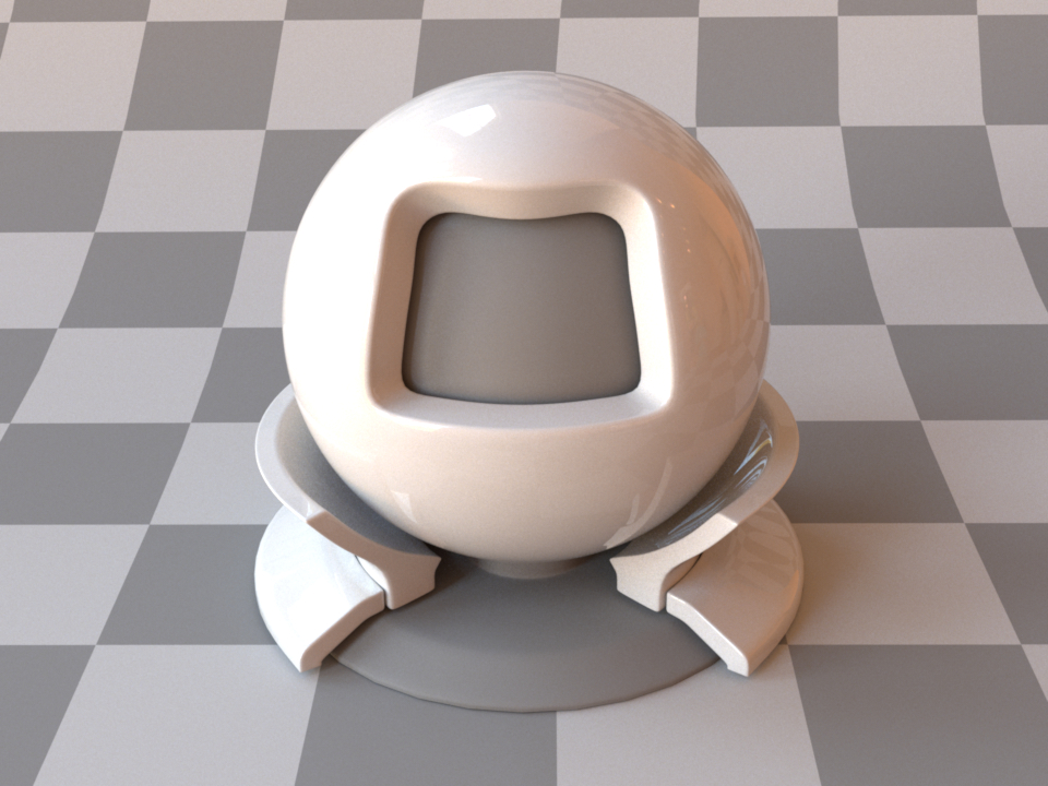
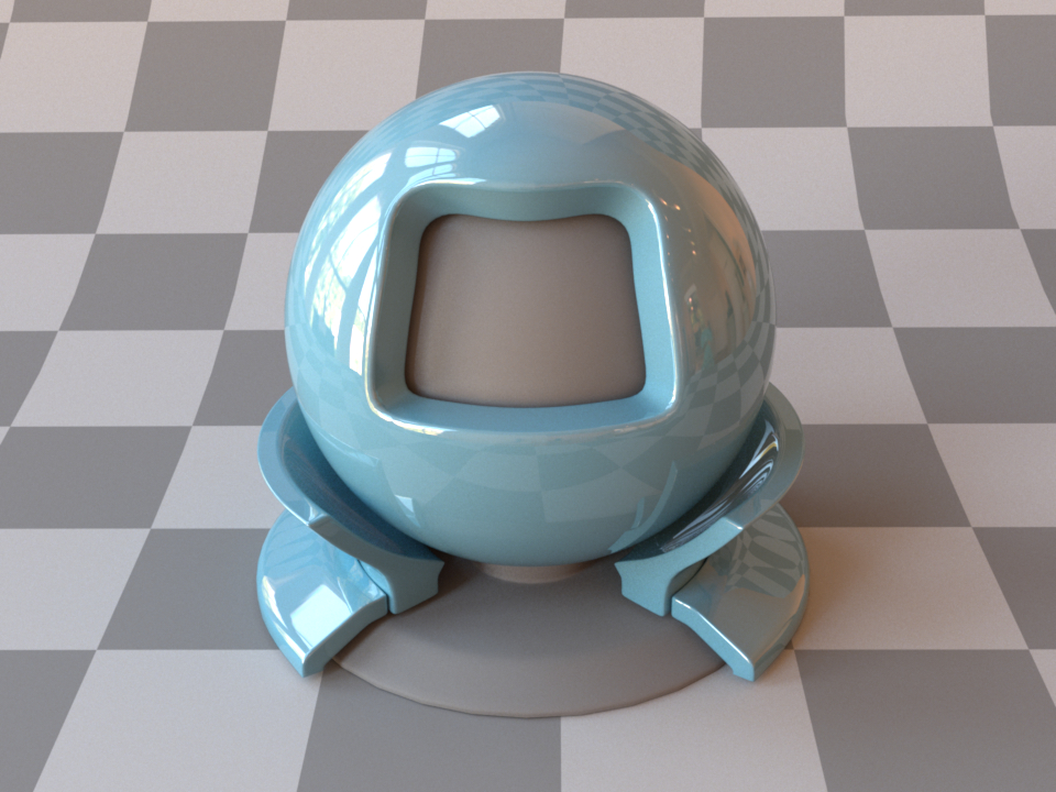
This plugin describes a smooth plastic-like material with internal scattering. It uses the Fresnel reflection and transmission coefficients to provide direction-dependent specular and diffuse components. Since it is simple, realistic, and fast, this model is often a better choice than the roughplastic plugins when rendering smooth plastic-like materials. For convenience, this model allows to specify IOR values either numerically, or based on a list of known materials (see the corresponding table in the dielectric reference). When no parameters are given, the plugin activates the defaults, which describe a white polypropylene plastic material.
The following XML snippet describes a shiny material whose diffuse reflectance is specified using sRGB:
<bsdf type="plastic">
    <rgb name="diffuse_reflectance" value="0.1, 0.27, 0.36"/>
    <float name="int_ior" value="1.9"/>
</bsdf>
'type': 'plastic',
'diffuse_reflectance': {
    'type': 'rgb',
    'value': [0.1, 0.27, 0.36]
},
'int_ior': 1.9
Internal scattering
Internally, tis model simulates the interaction of light with a diffuse base surface coated by a thin dielectric layer. This is a convenient abstraction rather than a restriction. In other words, there are many materials that can be rendered with this model, even if they might not fit this description perfectly well.

(a) At the boundary, incident illumination is partly reflected and refracted

(b) The refracted portion scatters diffusely at the base layer

(c) An illustration of the scattering events that are internally handled by this plugin
Given illumination that is incident upon such a material, a portion of the illumination is specularly reflected at the material boundary, which results in a sharp reflection in the mirror direction (a). The remaining illumination refracts into the material, where it scatters from the diffuse base layer (b). While some of the diffusely scattered illumination is able to directly refract outwards again, the remainder is reflected from the interior side of the dielectric boundary and will in fact remain trapped inside the material for some number of internal scattering events until it is finally able to escape (c).
Due to the mathematical simplicity of this setup, it is possible to work out the correct form of the model without actually having to simulate the potentially large number of internal scattering events.
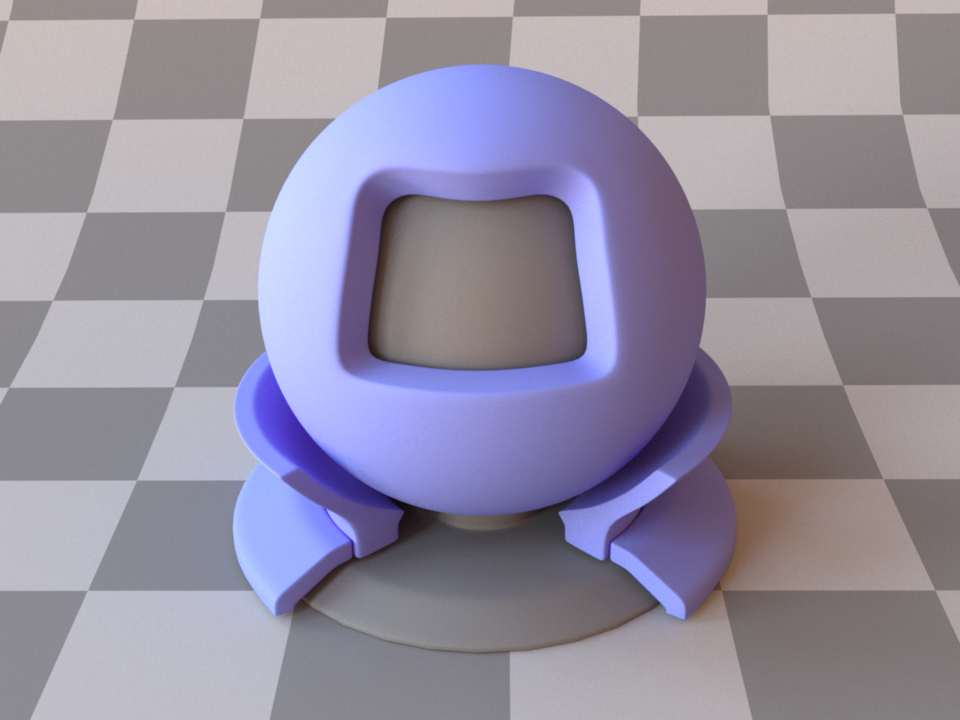
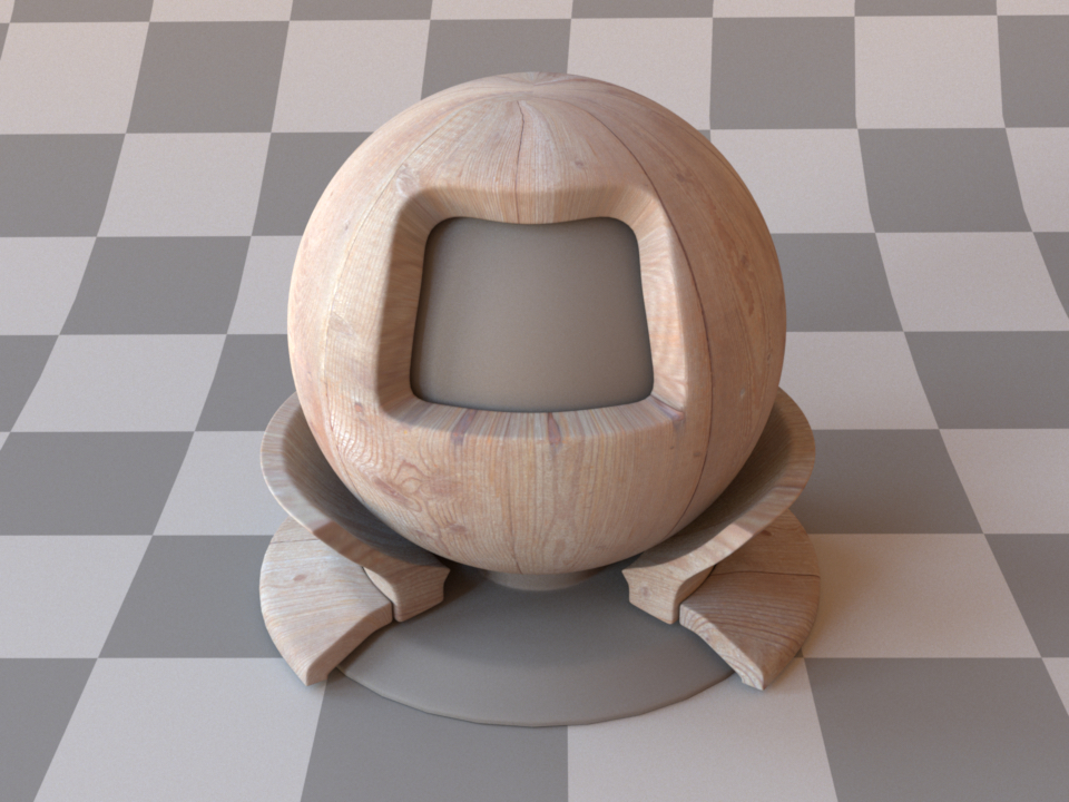
Note that due to the internal scattering, the diffuse color of the
material is in practice slightly different from the color of the
base layer on its own—in particular, the material color will tend to shift towards
darker colors with higher saturation. Since this can be counter-intuitive when
using bitmap textures, these color shifts are disabled by default. Specify
the parameter nonlinear=true to enable them. The following renderings
illustrate the resulting change:
This effect is also seen in real life, for instance a piece of wood will look slightly darker after coating it with a layer of varnish.
Rough plastic material (roughplastic)
Parameter |
Type |
Description |
Flags |
|---|---|---|---|
diffuse_reflectance |
spectrum or texture |
Optional factor used to modulate the diffuse reflection component. (Default: 0.5) |
P, ∂ |
nonlinear |
boolean |
Account for nonlinear color shifts due to internal scattering? See the plastic plugin for details. default{Don’t account for them and preserve the texture colors. (Default: false) |
|
int_ior |
float or string |
Interior index of refraction specified numerically or using a known material name. (Default: polypropylene / 1.49) |
|
ext_ior |
float or string |
Exterior index of refraction specified numerically or using a known material name. (Default: air / 1.000277) |
|
specular_reflectance |
spectrum or texture |
Optional factor that can be used to modulate the specular reflection component. Note that for physical realism, this parameter should never be touched. (Default: 1.0) |
P, ∂ |
distribution |
string |
Specifies the type of microfacet normal distribution used to model the surface roughness.
|
|
alpha |
float |
Specifies the roughness of the unresolved surface micro-geometry along the tangent and bitangent directions. When the Beckmann distribution is used, this parameter is equal to the root mean square (RMS) slope of the microfacets. (Default: 0.1) |
P, ∂, D |
sample_visible |
boolean |
Enables a sampling technique proposed by Heitz and D’Eon [HDEon14], which focuses computation on the visible parts of the microfacet normal distribution, considerably reducing variance in some cases. (Default: true, i.e. use visible normal sampling) |
|
State parameters |
|||
eta |
float |
Relative index of refraction from the exterior to the interior |
P, ∂, D |
This plugin implements a realistic microfacet scattering model for rendering rough dielectric materials with internal scattering, such as plastic.
Microfacet theory describes rough surfaces as an arrangement of unresolved and ideally specular facets, whose normal directions are given by a specially chosen microfacet distribution. By accounting for shadowing and masking effects between these facets, it is possible to reproduce the important off-specular reflections peaks observed in real-world measurements of such materials.
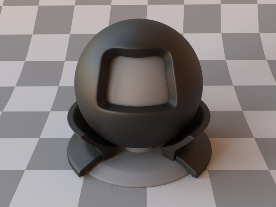
This plugin is essentially the roughened equivalent of the (smooth) plugin plastic. For very low values of \(\alpha\), the two will be identical, though scenes using this plugin will take longer to render due to the additional computational burden of tracking surface roughness.
For convenience, this model allows to specify IOR values either numerically, or based on a list of known materials (see the corresponding table in the dielectric reference). When no parameters are given, the plugin activates the defaults, which describe a white polypropylene plastic material with a light amount of roughness modeled using the Beckmann distribution.
To get an intuition about the effect of the surface roughness parameter \(\alpha\), consider the following approximate classification: a value of \(\alpha=0.001-0.01\) corresponds to a material with slight imperfections on an otherwise smooth surface finish, \(\alpha=0.1\) is relatively rough, and \(\alpha=0.3-0.7\) is extremely rough (e.g. an etched or ground finish). Values significantly above that are probably not too realistic.
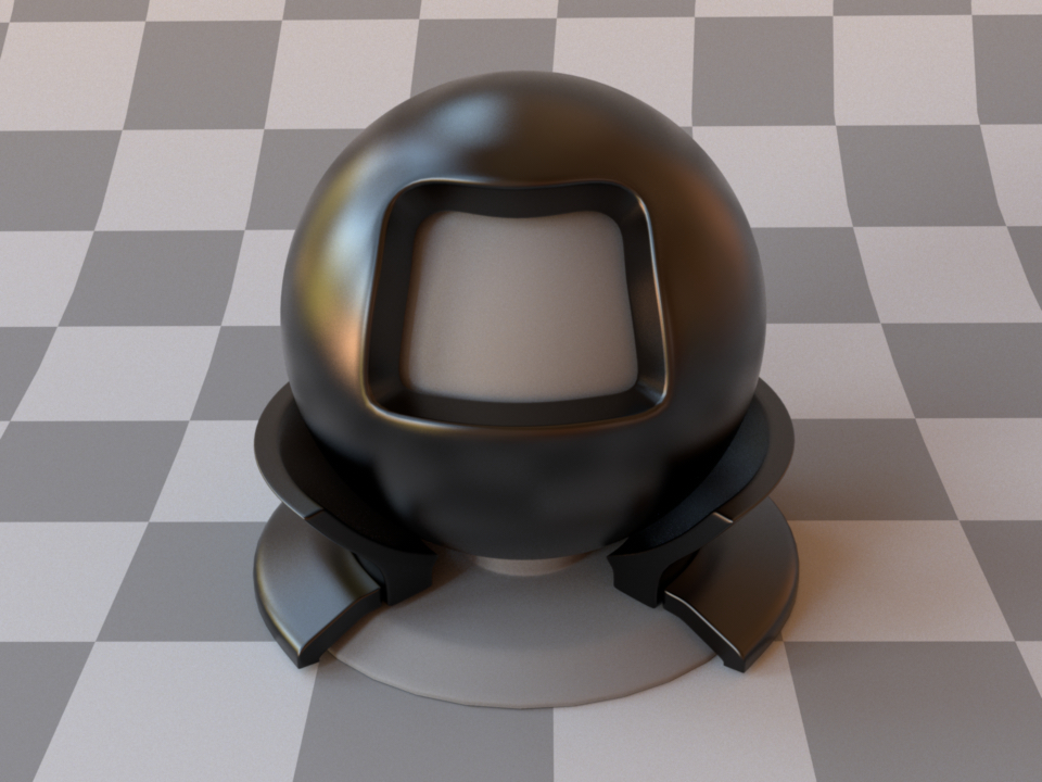
The following XML snippet describes a material definition for black plastic material.
<bsdf type="roughplastic">
    <string name="distribution" value="beckmann"/>
    <float name="int_ior" value="1.61"/>
    <rgb name="diffuse_reflectance" value="0"/>
</bsdf>
'type': 'roughplastic',
'distribution': 'beckmann',
'int_ior': 1.61,
'diffuse_reflectance': {
    'type': 'rgb',
    'value': 0
}
Like the plastic material, this model internally simulates the interaction of light with a diffuse base surface coated by a thin dielectric layer (where the coating layer is now rough). This is a convenient abstraction rather than a restriction. In other words, there are many materials that can be rendered with this model, even if they might not fit this description perfectly well.
The simplicity of this setup makes it possible to account for interesting nonlinear effects due to internal scattering, which is controlled by the nonlinear parameter:
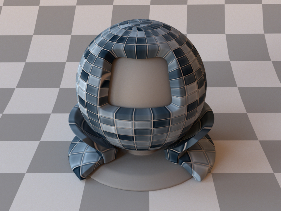
Diffuse textured rendering

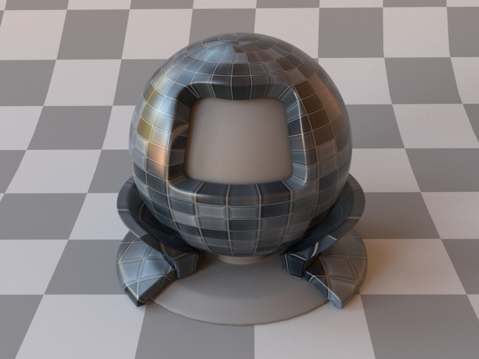
Rough plastic model with nonlinear=false
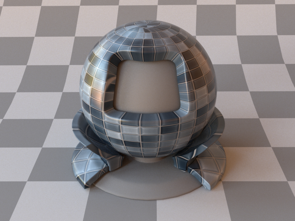
Textured rough plastic model with nonlinear=true
For more details, please refer to the description of this parameter given in the plastic plugin section.
Bump map BSDF adapter (bumpmap)
Parameter |
Type |
Description |
Flags |
|---|---|---|---|
(Nested plugin) |
texture |
Specifies the bump map texture. |
P, ∂, D |
(Nested plugin) |
bsdf |
A BSDF model that should be affected by the bump map |
P, ∂, D |
scale |
float |
Bump map gradient multiplier. (Default: 1.0) |
P |
flip_invalid_normals |
boolean |
If enabled, the plugin will ensure that the perturbed normals are always consistent with the geometric normal. This prevents visual artifacts and is achieved by a simply flipping the shading normal, as described in [SchusslerHHD17]. (Default: true) |
P |
use_shadowing_function |
boolean |
If enabled, the plugin uses a Microfacet-based shadowing term [ELS19] to smooth out transitions on shadow boundaries. (Default: true) |
P |
Bump mapping is a simple technique for cheaply adding surface detail to a rendering. This is done by perturbing the shading coordinate frame based on a displacement height field provided as a texture. This method can lend objects a highly realistic and detailed appearance (e.g. wrinkled or covered by scratches and other imperfections) without requiring any changes to the input geometry. The implementation in Mitsuba uses the common approach of ignoring the usually negligible texture-space derivative of the base mesh surface normal. As side effect of this decision, it is invariant to constant offsets in the height field texture: only variations in its luminance cause changes to the shading frame.
Note that the magnitude of the height field variations influences the scale of the displacement.
The following XML snippet describes a rough plastic material affected by a bump
map. Note that we set the raw properties of the bump map bitmap object to
true in order to disable the transformation from sRGB to linear encoding:
<bsdf type="bumpmap">
    <texture name="arbitrary" type="bitmap">
        <boolean name="raw" value="true"/>
        <string name="filename" value="textures/bumpmap.jpg"/>
    </texture>
    <bsdf type="roughplastic"/>
</bsdf>
'type': 'bumpmap',
'arbitrary': {
    'raw': True,
    'filename': 'textures/bumpmap.jpg'
},
'bsdf': {
    'type': 'roughplastic'
}
Normal map BSDF (normalmap)
Parameter |
Type |
Description |
Flags |
|---|---|---|---|
normalmap |
texture |
The color values of this texture specify the perturbed normals relative in the local surface coordinate system |
P, ∂, D |
(Nested plugin) |
bsdf |
A BSDF model that should be affected by the normal map |
P, ∂ |
flip_invalid_normals |
boolean |
If enabled, the plugin will ensure that the perturbed normals are always consistent with the geometric normal. This prevents visual artifacts and is achieved by a simply flipping the shading normal, as described in [SchusslerHHD17]. (Default: true) |
P |
use_shadowing_function |
boolean |
If enabled, the plugin uses a Microfacet-based shadowing term [ELS19] to smooth out transitions on shadow boundaries. (Default: true) |
P |
Normal mapping is a simple technique for cheaply adding surface detail to a rendering. This is done by perturbing the shading coordinate frame based on a normal map provided as a texture. This method can lend objects a highly realistic and detailed appearance (e.g. wrinkled or covered by scratches and other imperfections) without requiring any changes to the input geometry.

A normal map is a RGB texture, whose color channels encode the XYZ coordinates of the desired surface normals. These are specified relative to the local shading frame, which means that a normal map with a value of \((0,0,1)\) everywhere causes no changes to the surface. To turn the 3D normal directions into (nonnegative) color values suitable for this plugin, the mapping \(x \mapsto (x+1)/2\) must be applied to each component.
The following XML snippet describes a smooth mirror material affected by a normal map. Note that we set the
raw properties of the normal map bitmap object to true in order to disable the
transformation from sRGB to linear encoding:
<bsdf type="normalmap">
    <texture name="normalmap" type="bitmap">
        <boolean name="raw" value="true"/>
        <string name="filename" value="textures/normalmap.jpg"/>
    </texture>
    <bsdf type="roughplastic"/>
</bsdf>
'type': 'normalmap',
'normalmap': {
    'type': 'bitmap',
    'raw': True,
    'filename': 'textures/normalmap.jpg'
},
'bsdf': {
    'type': 'roughplastic'
}
Blended material (blendbsdf)
Parameter |
Type |
Description |
Flags |
|---|---|---|---|
weight |
float or texture |
A floating point value or texture with values between zero and one. The extreme values zero and one activate the first and second nested BSDF respectively, and in-between values interpolate accordingly. (Default: 0.5) |
P, ∂ |
(Nested plugin) |
bsdf |
Two nested BSDF instances that should be mixed according to the specified blending weight |
P, ∂ |
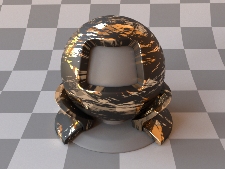
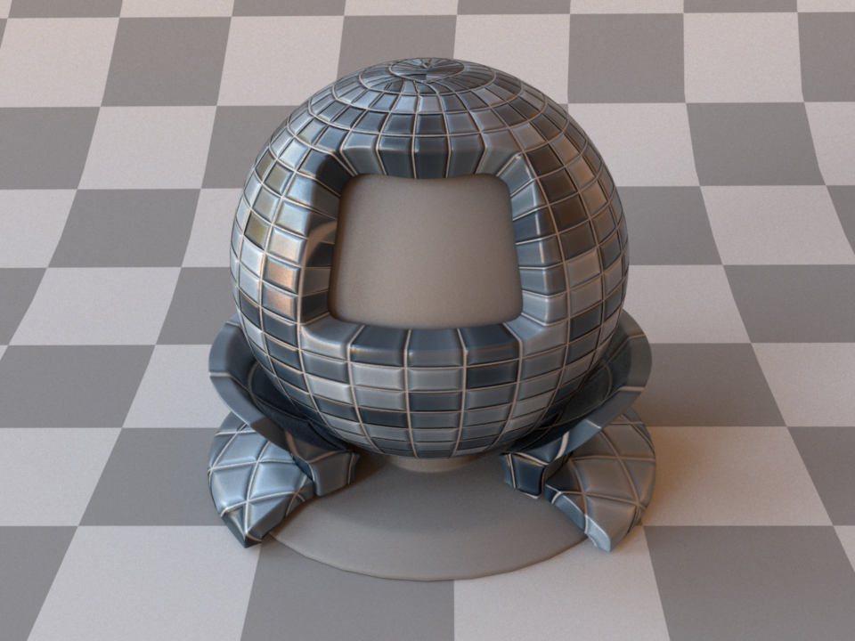
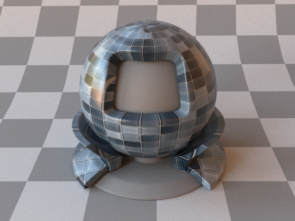
A material created by blending between rough plastic and smooth metal based on a binary bitmap texture
This plugin implements a blend material, which represents linear combinations of two BSDF instances. Any surface scattering model in Mitsuba 3 (be it smooth, rough, reflecting, or transmitting) can be mixed with others in this manner to synthesize new models. The association of nested BSDF plugins with the two positions in the interpolation is based on the alphanumeric order of their identifiers.
The following XML snippet describes the material shown above:
<bsdf type="blendbsdf">
    <texture name="weight" type="bitmap">
        <string name="filename" value="pattern.png"/>
    </texture>
    <bsdf type="conductor">
    </bsdf>
    <bsdf type="roughplastic">
        <rgb name="diffuse_reflectance" value="0.1"/>
    </bsdf>
</bsdf>
'type': 'blendbsdf',
'weight': {
    'type': 'bitmap',
    'filename': 'pattern.png'
},
'bsdf_0': {
    'type': 'conductor'
},
'bsdf_1': {
    'type': 'roughplastic',
    'diffuse_reflectance': 0.1
}
Opacity mask (mask)
Parameter |
Type |
Description |
Flags |
|---|---|---|---|
opacity |
spectrum or texture |
Specifies the opacity (where 1=completely opaque) (Default: 0.5) |
P, ∂, D |
(Nested plugin) |
bsdf |
A base BSDF model that represents the non-transparent portion of the scattering |
P, ∂ |
This plugin applies an opacity mask to add nested BSDF instance. It interpolates between perfectly transparent and completely opaque based on the opacity parameter.
The transparency is internally implemented as a forward-facing Dirac delta distribution. Note that the standard path tracer does not have a good sampling strategy to deal with this, but the (volumetric path tracer) does. It may thus be preferable when rendering scenes that contain the mask plugin, even if there is nothing volumetric in the scene.
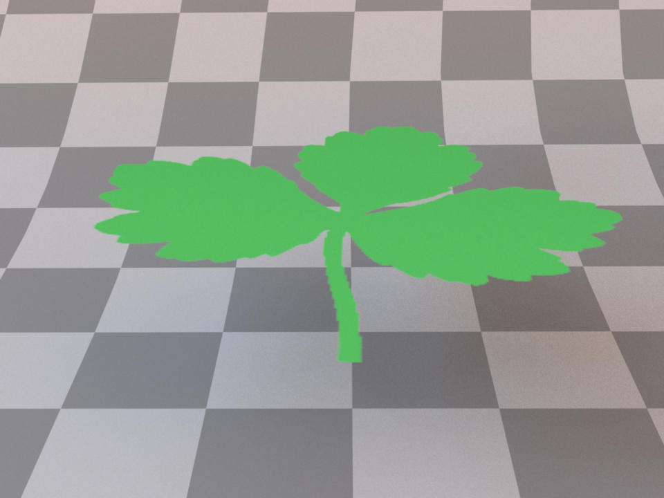
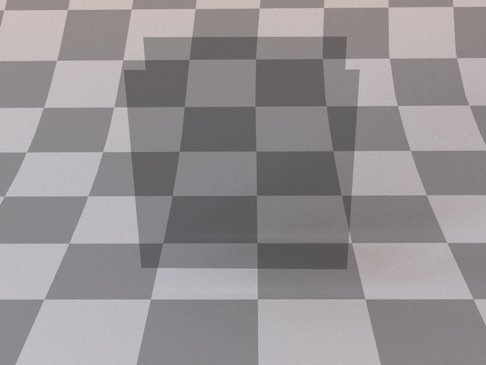
The following XML snippet describes a material configuration for a transparent leaf:
<bsdf type="mask">
    <!-- Base material: a two-sided textured diffuse BSDF -->
    <bsdf type="twosided">
        <bsdf type="diffuse">
            <texture name="reflectance" type="bitmap">
                <string name="filename" value="leaf.png"/>
            </texture>
        </bsdf>
    </bsdf>

    <!-- Fetch the opacity mask from a monochromatic texture -->
    <texture type="bitmap" name="opacity">
        <string name="filename" value="leaf_mask.png"/>
    </texture>
</bsdf>
'type': 'mask',
# Base material: a two-sided textured diffuse BSDF
'material': {
    'type': 'twosided',
    'bsdf': {
        'type': 'diffuse',
        'reflectance': {
            'type': 'bitmap',
            'filename': 'leaf.png'
        }
    }
},

# Fetch the opacity mask from a monochromatic texture
'opacity': {
    'type': 'texture',
    'filename': 'leaf_mask.png'
}
Two-sided BRDF adapter (twosided)
Parameter |
Type |
Description |
Flags |
|---|---|---|---|
(Nested plugin) |
bsdf |
A nested BRDF that should be turned into a two-sided scattering model. If two BRDFs are specified, they will be placed on the front and back side, respectively |
P, ∂ |
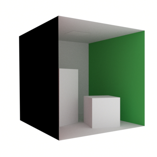
From this angle, the Cornell box scene shows visible back-facing geometry
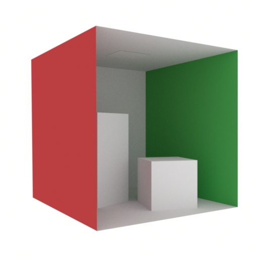
Applying the twosided plugin fixes the rendering
By default, all non-transmissive scattering models in Mitsuba 3 are one-sided — in other words, they absorb all light that is received on the interior-facing side of any associated surfaces. Holes and visible back-facing parts are thus exposed as black regions.
Usually, this is a good idea, since it will reveal modeling issues early on. But sometimes one is forced to deal with improperly closed geometry, where the one-sided behavior is bothersome. In that case, this plugin can be used to turn one-sided scattering models into proper two-sided versions of themselves. The plugin has no parameters other than a required nested BSDF specification. It is also possible to supply two different BRDFs that should be placed on the front and back side, respectively.
The following snippet describes a two-sided diffuse material:
<bsdf type="twosided">
    <bsdf type="diffuse">
         <rgb name="reflectance" value="0.4"/>
    </bsdf>
</bsdf>
'type': 'twosided',
'material': {
    'type': 'diffuse',
    'reflectance': {
        'type': 'rgb',
        'value': 0.4
    }
}
Null material (null)
This plugin models a completely invisible surface material. Light will not interact with this BSDF in any way.
Internally, this is implemented as a forward-facing Dirac delta distribution. Note that the standard path tracer does not have a good sampling strategy to deal with this, but the (volumetric path tracer) does.
The main purpose of this material is to be used as the BSDF of a shape enclosing a participating medium.
Linear polarizer material (polarizer)
Parameter |
Type |
Description |
Flags |
|---|---|---|---|
theta |
spectrum or texture |
Specifies the rotation angle (in degrees) of the polarizer around the optical axis (Default: 0.0) |
P, ∂, D |
transmittance |
spectrum or texture |
Optional factor that can be used to modulate the specular transmission. (Default: 1.0) |
P, ∂ |
polarizing |
boolean |
Optional flag to disable polarization changes in order to use this as a neutral density filter, even in polarized render modes. (Default: true, i.e. act as polarizer) |
This material simulates an ideal linear polarizer useful to test polarization aware
light transport or to conduct virtual optical experiments. The absorbing axis of the
polarizer is aligned with the V-direction of the underlying surface parameterization.
To rotate the polarizer, either the parameter theta can be used, or alternative
a rotation can be applied directly to the associated shape.
Two aligned polarizers. The average intensity is reduced by a factor of 2.
Two polarizers offset by 90 degrees. All transmitted light is absorbed.
Two polarizers offset by 90 degrees, with a third polarizer in between at 45 degrees. Some light is transmitted again.
The following XML snippet describes a linear polarizer material with a rotation of 90 degrees.
<bsdf type="polarizer">
    <spectrum name="theta" value="90"/>
</bsdf>
'type': 'polarizer',
'theta': {
    'type': 'spectrum',
    'value': 90
}
Apart from a change of polarization, light does not interact with this material in any way and does not change its direction. Internally, this is implemented as a forward-facing Dirac delta distribution. Note that the standard path tracer does not have a good sampling strategy to deal with this, but the (volumetric path tracer) does.
In unpolarized rendering modes, the behavior defaults to a non-polarizing transmitting material that absorbs 50% of the incident illumination.
Linear retarder material (retarder)
Parameter |
Type |
Description |
Flags |
|---|---|---|---|
theta |
spectrum or texture |
Specifies the rotation angle (in degrees) of the retarder around the optical axis (Default: 0.0) |
P, ∂ |
delta |
spectrum or texture |
Specifies the retardance (in degrees) where 360 degrees is equivalent to a full wavelength. (Default: 90.0) |
P, ∂ |
transmittance |
spectrum or texture |
Optional factor that can be used to modulate the specular transmission. (Default: 1.0) |
P, ∂ |
This material simulates an ideal linear retarder useful to test polarization aware light transport or to conduct virtual optical experiments. The fast axis of the retarder is aligned with the U-direction of the underlying surface parameterization. For non-perpendicular incidence, a cosine falloff term is applied to the retardance.
This plugin can be used to instantiate the common special cases of
half-wave plates (with delta=180) and quarter-wave plates (with delta=90).
The following XML snippet describes a quarter-wave plate material:
<bsdf type="retarder">
    <spectrum name="delta" value="90"/>
</bsdf>
'type': 'retarder',
'delta': {
    'type': 'spectrum',
    'value': 90
}
Apart from a change of polarization, light does not interact with this material in any way and does not change its direction. Internally, this is implemented as a forward-facing Dirac delta distribution. Note that the standard path tracer does not have a good sampling strategy to deal with this, but the (volumetric path tracer) does.
In unpolarized rendering modes, the behavior defaults to non-polarizing transparent material similar to the null BSDF plugin.
Circular polarizer material (circular)
Parameter |
Type |
Description |
Flags |
|---|---|---|---|
transmittance |
spectrum or texture |
Optional factor that can be used to modulate the specular transmission. (Default: 1.0) |
P, ∂ |
left_handed |
boolean |
Flag to switch between left and right circular polarization. (Default: false, i.e. right circular polarizer) |
This material simulates an ideal circular polarizer useful to test polarization aware
light transport or to conduct virtual optical experiments. Unlike the
linear retarder or the linear polarizer,
this filter is invariant to rotations and therefore does not provide a corresponding
theta parameter.
The following XML snippet describes a left circular polarizer material:
<bsdf type="circular">
    <boolean name="left_handed" value="true"/>
</bsdf>
'type': 'circular',
'left_handed': True
Apart from a change of polarization, light does not interact with this material in any way and does not change its direction. Internally, this is implemented as a forward-facing Dirac delta distribution. Note that the standard path tracer does not have a good sampling strategy to deal with this, but the (volumetric path tracer) does.
In unpolarized rendering modes, the behavior defaults to non-polarizing transparent material similar to the null BSDF plugin.
Polarized plastic material (pplastic)
Parameter |
Type |
Description |
Flags |
|---|---|---|---|
diffuse_reflectance |
spectrum or texture |
Optional factor used to modulate the diffuse reflection component. (Default: 0.5) |
P, ∂ |
specular_reflectance |
spectrum or texture |
Optional factor that can be used to modulate the specular reflection component. Note that for physical realism, this parameter should never be touched. (Default: 1.0) |
P, ∂ |
int_ior |
float or string |
Interior index of refraction specified numerically or using a known material name. (Default: polypropylene / 1.49) |
|
ext_ior |
float or string |
Exterior index of refraction specified numerically or using a known material name. (Default: air / 1.000277) |
|
distribution |
string |
Specifies the type of microfacet normal distribution used to model the surface roughness.
|
|
alpha |
float or texture |
Specifies the roughness of the unresolved surface micro-geometry along the tangent and bitangent directions. When the Beckmann distribution is used, this parameter is equal to the root mean square (RMS) slope of the microfacets. (Default: 0.1) |
P, ∂, D |
sample_visible |
boolean |
Enables a sampling technique proposed by Heitz and D’Eon [HDEon14], which focuses computation on the visible parts of the microfacet normal distribution, considerably reducing variance in some cases. (Default: true, i.e. use visible normal sampling) |
|
State parameters |
|||
eta |
float or texture |
Relative index of refraction from the exterior to the interior |
P, ∂, D |
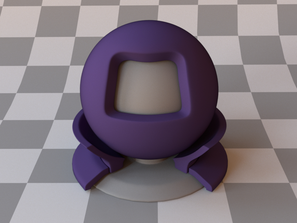
This plugin implements a scattering model that combines diffuse and specular reflection where both components can interact with polarized light. This is based on the pBRDF proposed in “Simultaneous Acquisition of Polarimetric SVBRDF and Normals” by Baek et al. 2018 ([BJTK18]).
Apart from the polarization support, this is similar to the plastic and roughplastic plugins. There, the interaction of light with a diffuse base surface coated by a (potentially rough) thin dielectric layer is used as a way of combining the two components, whereas here the two are added in a more ad-hoc way:
The specular component is a standard rough reflection from a microfacet model.
The diffuse Lambert component is attenuated by a smooth refraction into and out of the material where conceptually some subsurface scattering occurs in between that causes the light to escape in a diffused way.
This is illustrated in the following diagram:

The intensity of the rough reflection is always less than the light lost by the two refractions which means the addition of these components does not result in any extra energy. However, it is also not energy conserving.
What makes this plugin particularly interesting is that both components account for the polarization state of light when it interacts with the material. For applications without the need of polarization support, it is recommended to stick to the standard plastic and roughplastic plugins.
See the following images of the two components rendered individually together with false-color visualizations of the resulting “\(\mathbf{s}_1\)” Stokes vector output that encodes horizontal vs. vertical linear polarization.
Specular component
Diffuse component
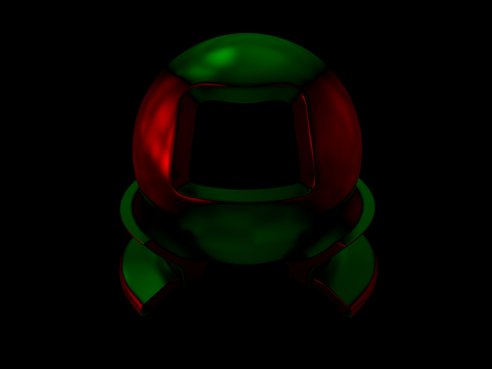
“\(\mathbf{s}_1\)” for the specular component
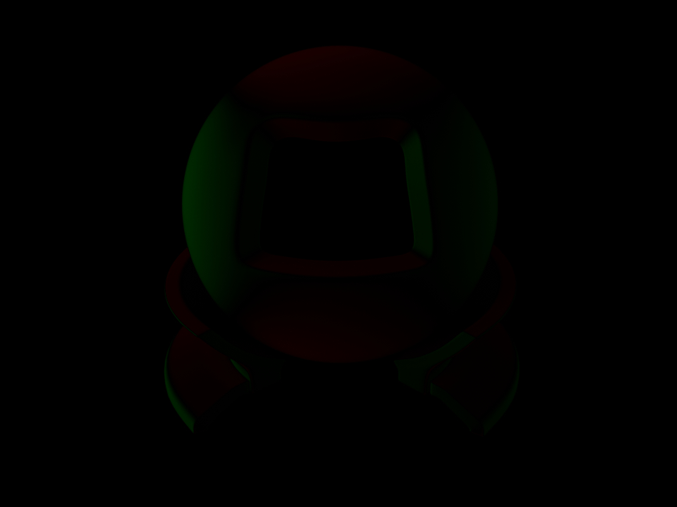
“\(\mathbf{s}_1\)” for the diffuse component
Note how the diffuse polarization is comparatively weak and has its orientation flipped by 90 degrees. This is a property that is commonly exploited in shape from polarization applications ([KTSR17]).
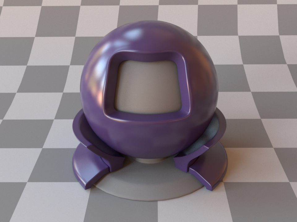
The following XML snippet describes the purple material from the test scene above:
<bsdf type="pplastic">
    <rgb name="diffuse_reflectance" value="0.05, 0.03, 0.1"/>
    <float name="alpha" value="0.06"/>
</bsdf>
'type': 'pplastic',
'diffuse_reflectance': {
    'type': 'rgb',
    'value': [0.05, 0.03, 0.1]
},
'alpha': 0.06
The Principled BSDF (principled)
Parameter |
Type |
Description |
Flags |
|---|---|---|---|
base_color |
spectrum or texture |
The color of the material. (Default:0.5) |
P, ∂ |
roughness |
float or texture |
Controls the roughness parameter of the main specular lobes. (Default:0.5) |
P, ∂, D |
anisotropic |
float or texture |
Controls the degree of anisotropy. (0.0 : isotropic material) (Default:0.0) |
P, ∂, D |
metallic |
texture or float |
The “metallicness” of the model. (Default:0.0) |
P, ∂, D |
spec_trans |
texture or float |
Blends BRDF and BSDF major lobe. (1.0: only BSDF response, 0.0 : only BRDF response.) (Default: 0.0) |
P, ∂, D |
eta |
float |
Interior IOR/Exterior IOR |
P, ∂, D |
specular |
float |
Controls the Fresnel reflection coefficient. This parameter has one to one
correspondence with |
P, ∂, D |
spec_tint |
texture or float |
The fraction of |
P, ∂ |
sheen |
float or texture |
The rate of the sheen lobe. (Default:0.0) |
P, ∂ |
sheen_tint |
float or texture |
The fraction of |
P, ∂ |
flatness |
float or texture |
Blends between the diffuse response and fake subsurface approximation based on Hanrahan-Krueger approximation. (0.0:only diffuse response, 1.0:only fake subsurface scattering.) (Default:0.0) |
P, ∂ |
clearcoat |
texture or float |
The rate of the secondary isotropic specular lobe. (Default:0.0) |
P, ∂, D |
clearcoat_gloss |
texture or float |
Controls the roughness of the secondary specular lobe. Clearcoat response gets glossier as the parameter increases. (Default:0.0) |
P, ∂, D |
diffuse_reflectance_sampling_rate |
float |
The rate of the cosine hemisphere reflection in sampling. (Default:1.0) |
P |
main_specular_sampling_rate |
float |
The rate of the main specular lobe in sampling. (Default:1.0) |
P |
clearcoat_sampling_rate |
float |
The rate of the secondary specular reflection in sampling. (Default:0.0) |
P |
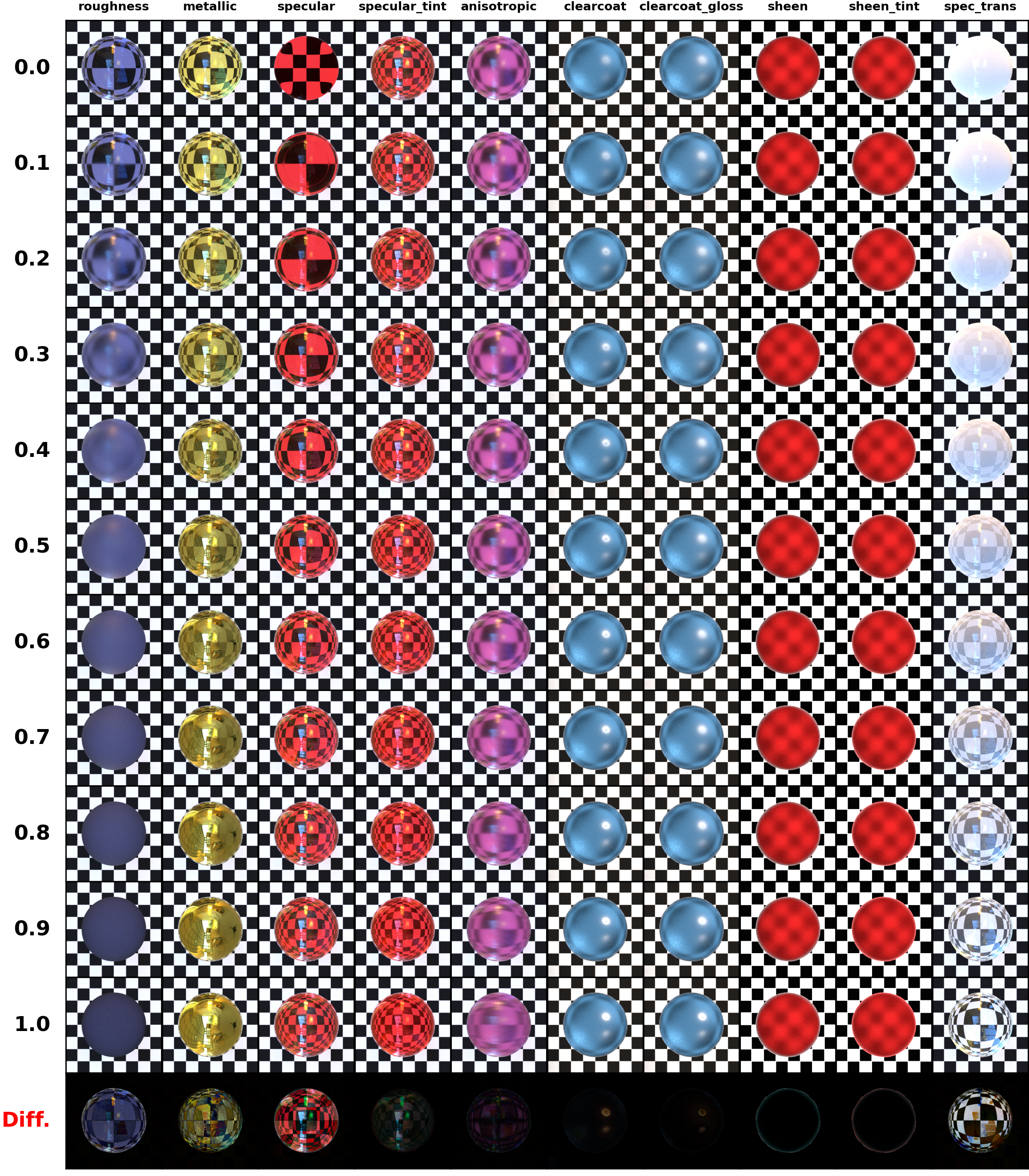
The principled BSDF is a complex BSDF with numerous reflective and transmissive lobes. It is able to produce great number of material types ranging from metals to rough dielectrics. Moreover, the set of input parameters are designed to be artist-friendly and do not directly correspond to physical units.
The implementation is based on the papers Physically Based Shading at Disney [Bur12] and Extending the Disney BRDF to a BSDF with Integrated Subsurface Scattering [Bur15] by Brent Burley.
Note
Subsurface scattering and volumetric extinction is not supported!
Images below show how the input parameters affect the appearance of the objects while one of the parameters is changed for each column.
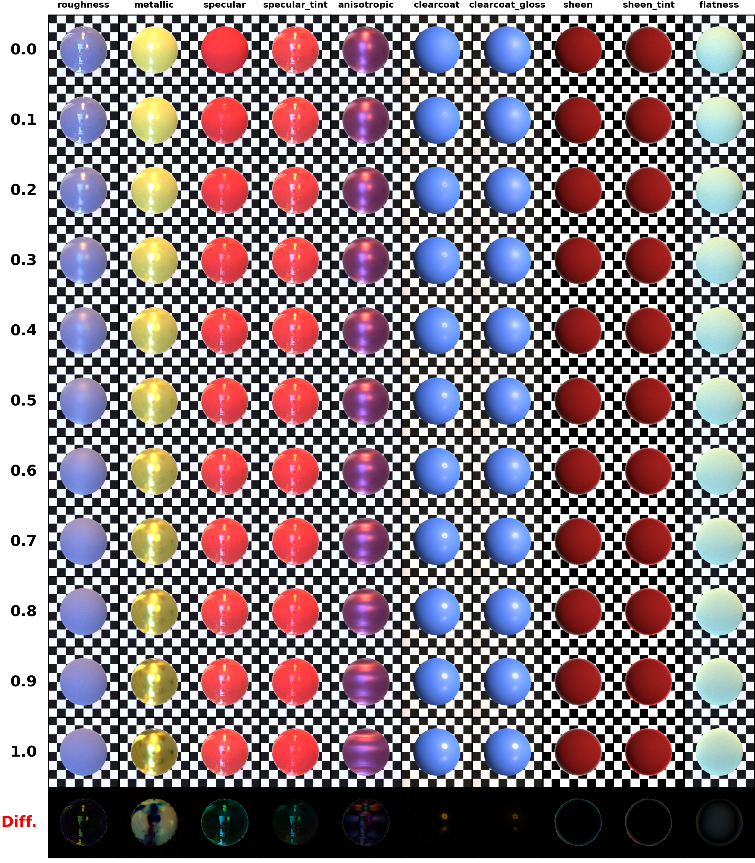
Blending of parameters when transmission lobe is turned off.
Blending of parameters when transmission lobe is turned on.
You can see the general structure of the BSDF below.
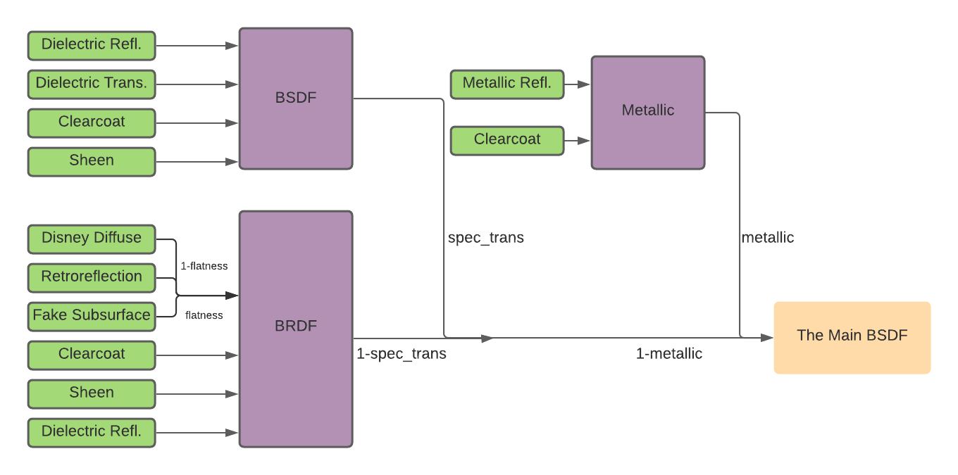
The general structure of the principled BSDF
The following XML snippet describes a material definition for principled material:
<bsdf type="principled">
    <rgb name="base_color" value="1.0,1.0,1.0"/>
    <float name="metallic" value="0.7" />
    <float name="specular" value="0.6" />
    <float name="roughness" value="0.2" />
    <float name="spec_tint" value="0.4" />
    <float name="anisotropic" value="0.5" />
    <float name="sheen" value="0.3" />
    <float name="sheen_tint" value="0.2" />
    <float name="clearcoat" value="0.6" />
    <float name="clearcoat_gloss" value="0.3" />
    <float name="spec_trans" value="0.4" />
</bsdf>
'type': 'principled',
'base_color': {
    'type': 'rgb',
    'value': [1.0, 1.0, 1.0]
},
'metallic': 0.7,
'specular': 0.6,
'roughness': 0.2,
'spec_tint': 0.4,
'anisotropic': 0.5,
'sheen': 0.3,
'sheen_tint': 0.2,
'clearcoat': 0.6,
'clearcoat_gloss': 0.3,
'spec_trans': 0.4
All of the parameters except sampling rates and eta should take values
between 0.0 and 1.0.
The Thin Principled BSDF (principledthin)
Parameter |
Type |
Description |
Flags |
|---|---|---|---|
base_color |
spectrum or texture |
The color of the material. (Default: 0.5) |
P, ∂ |
roughness |
float or texture |
Controls the roughness parameter of the main specular lobes. (Default: 0.5) |
P, ∂, D |
anisotropic |
float or texture |
Controls the degree of anisotropy. (0.0: isotropic material) (Default: 0.0) |
P, ∂, D |
spec_trans |
texture or float |
Blends diffuse and specular responses. (1.0: only specular response, 0.0 : only diffuse response.)(Default: 0.0) |
P, ∂ |
eta |
float or texture |
Interior IOR/Exterior IOR (Default: 1.5) |
P, ∂, D |
spec_tint |
texture or float |
The fraction of |
P, ∂ |
sheen |
float or texture |
The rate of the sheen lobe. (Default: 0.0) |
P, ∂ |
sheen_tint |
float or texture |
The fraction of |
P, ∂ |
flatness |
float or texture |
Blends between the diffuse response and fake subsurface approximation based on Hanrahan-Krueger approximation. (0.0:only diffuse response, 1.0:only fake subsurface scattering.) (Default: 0.0) |
P, ∂ |
diff_trans |
texture or float |
The fraction that the energy of diffuse reflection is given to the transmission. (0.0: only diffuse reflection, 2.0: only diffuse transmission) (Default:0.0) |
P, ∂ |
diffuse_reflectance_sampling_rate |
float |
The rate of the cosine hemisphere reflection in sampling. (Default: 1.0) |
P |
specular_reflectance_sampling_rate |
float |
The rate of the main specular reflection in sampling. (Default: 1.0) |
P |
specular_transmittance_sampling_rate |
float |
The rate of the main specular transmission in sampling. (Default: 1.0) |
P |
diffuse_transmittance_sampling_rate |
float |
The rate of the cosine hemisphere transmission in sampling. (Default: 1.0) |
P |
The thin principled BSDF is a complex BSDF which is designed by approximating some features of thin, translucent materials. The implementation is based on the papers Physically Based Shading at Disney [Bur12] and Extending the Disney BRDF to a BSDF with Integrated Subsurface Scattering [Bur15] by Brent Burley.
Images below show how the input parameters affect the appearance of the objects while one of the parameters is changed for each row.
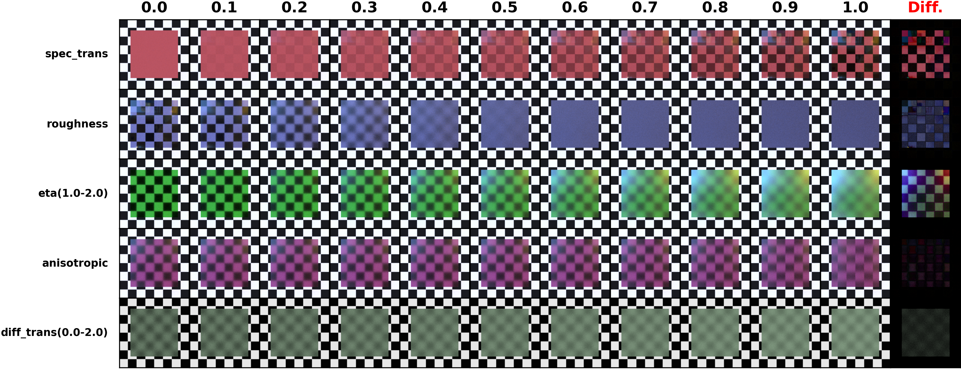
Blending of parameters
You can see the general structure of the BSDF below.
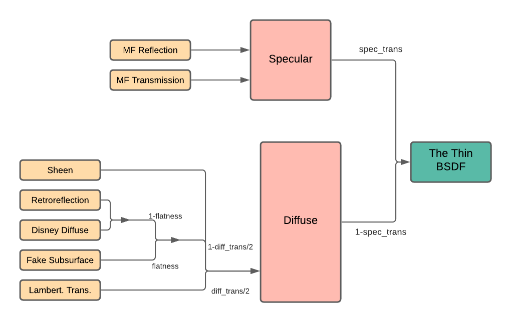
The general structure of the thin principled BSDF
The following XML snippet describes a material definition for principledthin material:
<bsdf type="principledthin">
    <rgb name="base_color" value="0.7,0.1,0.1 "/>
    <float name="roughness" value="0.15" />
    <float name="spec_tint" value="0.1" />
    <float name="anisotropic" value="0.5" />
    <float name="spec_trans" value="0.8" />
    <float name="diff_trans" value="0.3" />
    <float name="eta" value="1.33" />
</bsdf>
'type': 'principledthin',
'base_color': {
    'type': 'rgb',
    'value': [0.7, 0.1, 0.1]
},
'roughness': 0.15,
'spec_tint': 0.1,
'anisotropic': 0.5,
'spec_trans': 0.8,
'diff_trans': 0.3,
'eta': 1.33
All of the parameters, except sampling rates, diff_trans and
eta, should take values between 0.0 and 1.0. The range of
diff_trans is 0.0 to 2.0.